Interrupt, error and system messages
9.2 PROFINET IO
ET 200M
218 Operating Instructions, 12/2008, EWA-4NEB780600602-08
9.2 PROFINET IO
9.2.1 Diagnostics using LED display on IM 153-4 PN interface module
LED display
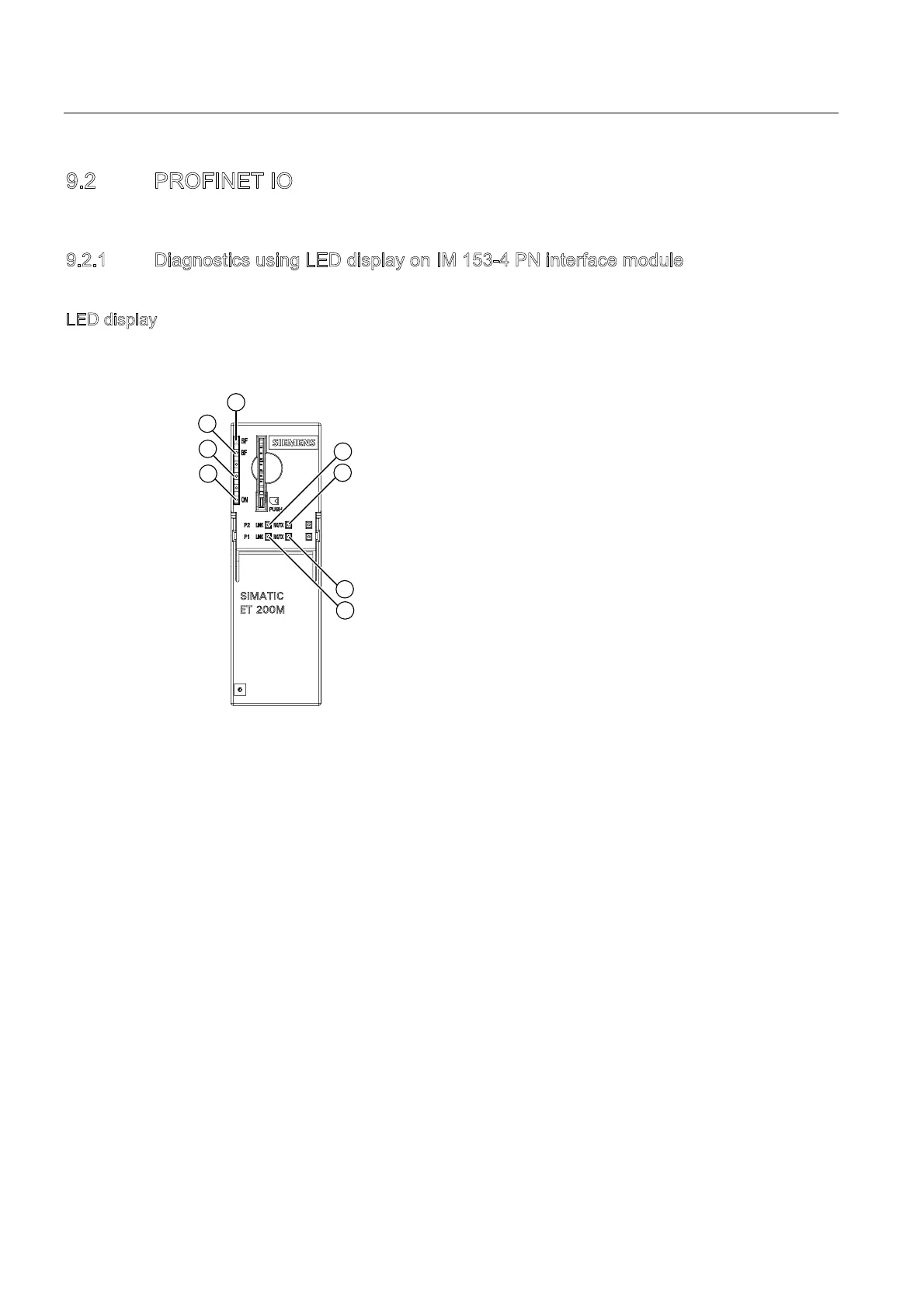
The figure below shows the position and arrangement of the LED display on the IM 153-
4 PN interface module:
① ON Supply voltage 1L+ (green LED)
② MT Maintenance (yellow LED)
③ BF Bus monitoring, red LED
④ SF Group error, red LED
⑤ LINK PROFINET IO Port 2, connection active (green LED)
⑥ RX/TX PROFINET IO Port 2, data exchange (yellow LED)
⑦ RX/TX PROFINET IO Port 1, data exchange (yellow LED)
⑧ LINK PROFINET IO Port 1, connection active (green LED)

 Loading...