Assignment planning
3.5 Configuring the mechanical structure
ET 200M
46 Operating Instructions, 12/2008, EWA-4NEB780600602-08
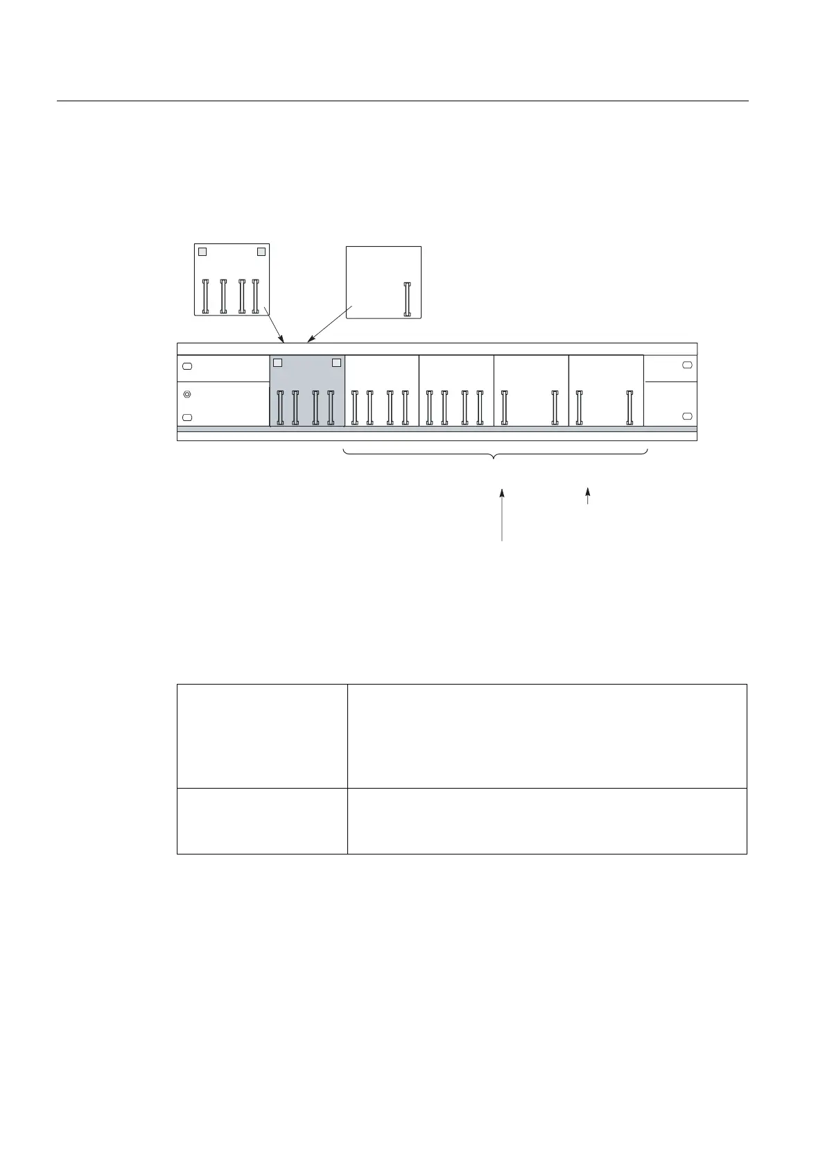
Installation Options
Dependent on the length of the rails you can fit up to 9 active bus modules:
%0 %0 %0 %0
%0,0,0
%036,0
%0
5HGXQGDQFHZLWK
[,0
,0[IRUಯ0RGXOHV
FKDQJHLQRSHUDWLRQರ
PD[LPXP%0[RU%0[
IRU[PPZLGH,2PRGXOHV
60)0KHUH\RXUHTXLUHPD[LPXPEXV
0RGXOHVIRUDQ(70
IRUPPZLGH,2
0RGXOHV60)0&3
Figure 3-9 Configuration with active bus modules
Placement of the PS 307 power supply modules
Redundancy with 2 x IM
153-2
If you use the 530 mm rail, place the BM IM/IM in the right-hand of the
two latched positions on the rail Then you can install either 2 x PS
307; 2A or 1 x PS 307; 5A to the rail to the left of the BM IM/IM.
Otherwise you must fit the power supply modules to a separate S7
standard rail.
Recommendation: Each IM 153-2 has its own PS.
IM 153-1 /-2 for "Module
change in operation"
Alongside the IM 153-x, the PS 307; 2A is also compatible with the
BM PS/IM.
The PS 307; 5A or 10A are not compatible with the BM PS/IM. You
must fit these to a separate S7 standard rail.
See also
Order Numbers for the ET 200M (Page 247)