Connecting
5.3 Connecting PROFINET IO
ET 200M
76 Operating Instructions, 12/2008, EWA-4NEB780600602-08
Required accessories
● Cable with maximum 2.5 mm
2
conductor cross section for the supply voltage
● PROFINET connector according to the specifications in the "PROFINET installation
guideline (http://www.profibus.com/pall/meta/downloads/article/00328/
)".
The following are suitable:
PROFINET RJ45 connector with
Fast Connect connection system,
180° cable outlet
6GK1901-1BB10-2AA0
● Industrial Ethernet Fast Connect installation cables
The following are suitable:
Fast Connect standard cable 6XV1840-2AH10
Fast Connect trailing cable 6XV1840-3AH10
Fast Connect marine cable 6XV1840-4AH10
Installing the PROFINET cable connector
Install the PROFINET connector according to the specifications in the "PROFINET
installation guideline (http://www.profibus.com/pall/meta/downloads/article/00328/
)".
For more information, refer to the "PROFINET Cabling and Interconnection Technology
(http://www.profibus.com/pall/meta/downloads/article/00327/
)" manual.
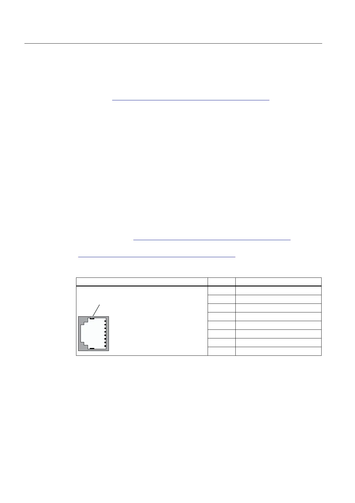
Pin assignment of the RJ45 connector
View of the RJ45 socket Terminal Assignment
1 RD (Receive Data +)
2 RD_N (Receive Data –)
3 TD (Transmit Data +)
4 Ground
5 Ground
6 TD_N (Transmit Data –)
7 Ground
6KLHOG
8 Ground
Installing the cable holder
Install the supplied cable holder (see figure above).
1. Open the front door of the IM 153-4 PN interface module.
2. Insert the cable holder into the prepared cutout on the interface module.
3. Screw the cable holder firmly into place.

 Loading...