EasyManuals Logo

Siemens SIMATIC ET 200PA SMART User Manual

Siemens SIMATIC ET 200PA SMART
226 pages
To Next Page IconTo Next Page
To Previous Page IconTo Previous Page
Page #131 background imageLoading...
Page #131 background image
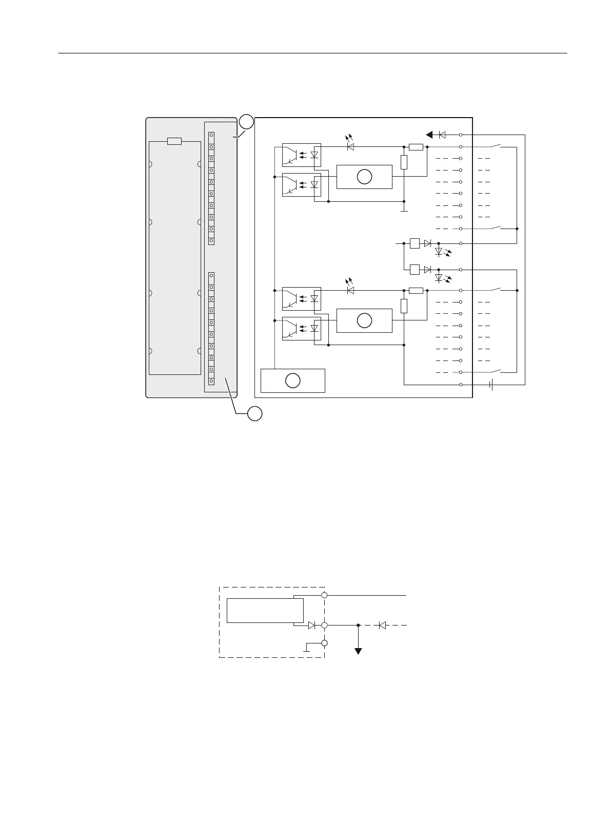
Wiring and block diagram of the DI 16 x DC 24 V
6)
9
V
9
V

9
V
9
V
/
/
/






9
0
0
Channel number
Group error display red (F LED)
Backplane bus interface
Wire-break detection
Wiring diagram for redundant sensor supply
The figure below shows how sensors can be additionally supplied with a redundant voltage
source using Vs.
/
/
9V
0
/
6KRUWFLUFXLWSURRI
GULYHU
'LJLWDOLQSXW
PRGXOH
7RWKHVHQVRUV
Figure 10-1 Wiring diagram for the redundant supply of sensors of the DI 16 x DC 24 V
ET 200PA SMART I/O modules
10.2 Digital input modules
ET 200PA SMART
Operating Instructions, 06/2019, A5E34192013-AB 131

Table of Contents

Questions and Answers:

Question and Answer IconNeed help?

Do you have a question about the Siemens SIMATIC ET 200PA SMART and is the answer not in the manual?

Siemens SIMATIC ET 200PA SMART Specifications

General IconGeneral
BrandSiemens
ModelSIMATIC ET 200PA SMART
CategoryControl Systems
LanguageEnglish

Related product manuals