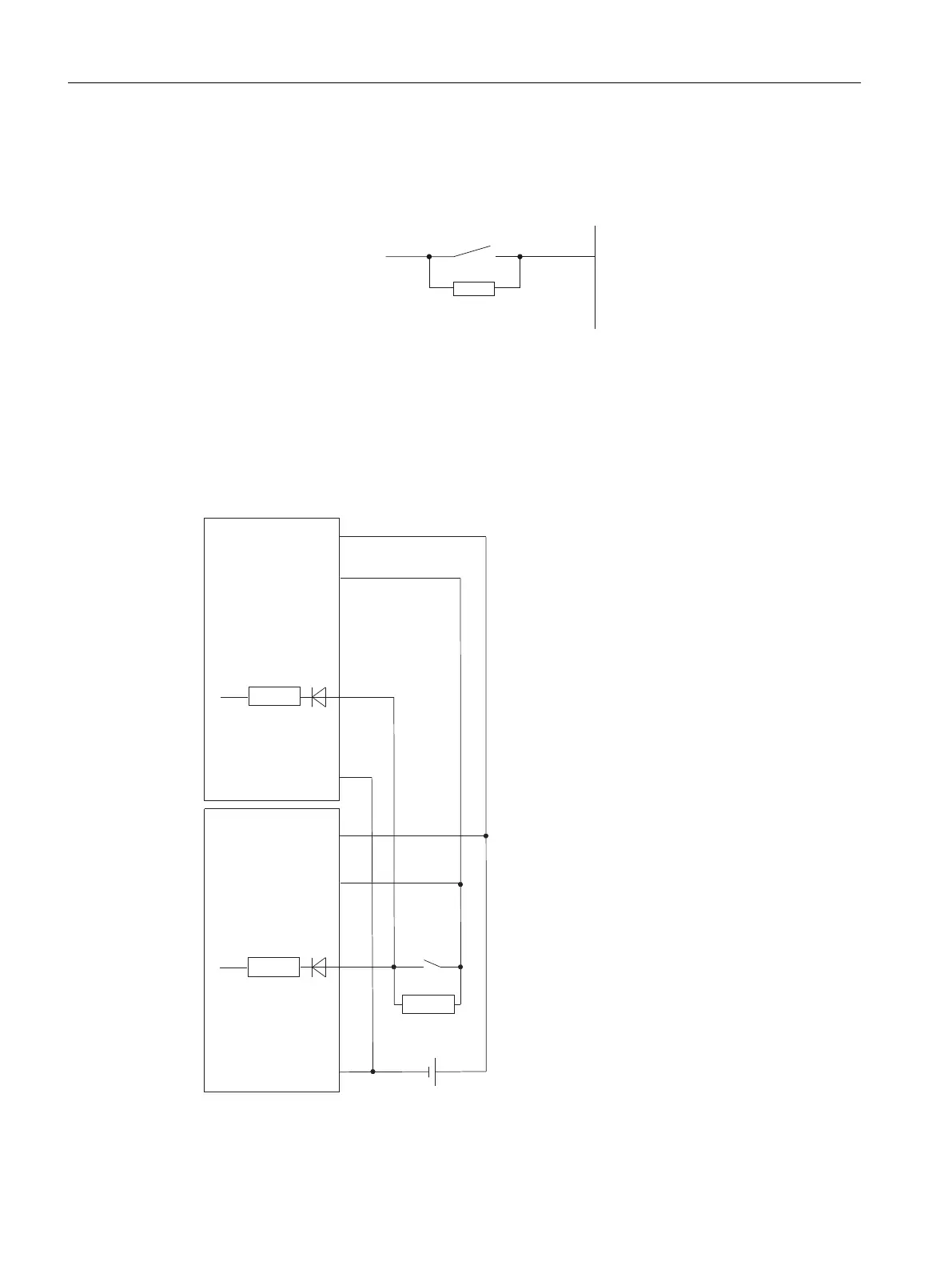
Wiring diagram for resistance circuit of the sensors
For wire-break detection, it is necessary to connect sensor contacts with a resistor even in case
of "0" signal.
([[
/9
V
NവNവ
Figure 10-2 Wiring diagram for resistance circuit of the sensors of the DI 16 x DC 24 V
Redundant use
The inputs can be operated redundantly without external connection of diodes.
0
/
9
&+[
&+[
0
/
N˖N˖
9V
9V
0RGXOH
0RGXOH
ET 200PA SMART I/O modules
10.2 Digital input modules
ET 200PA SMART
132 Operating Instructions, 06/2019, A5E34192013-AB
 Loading...


