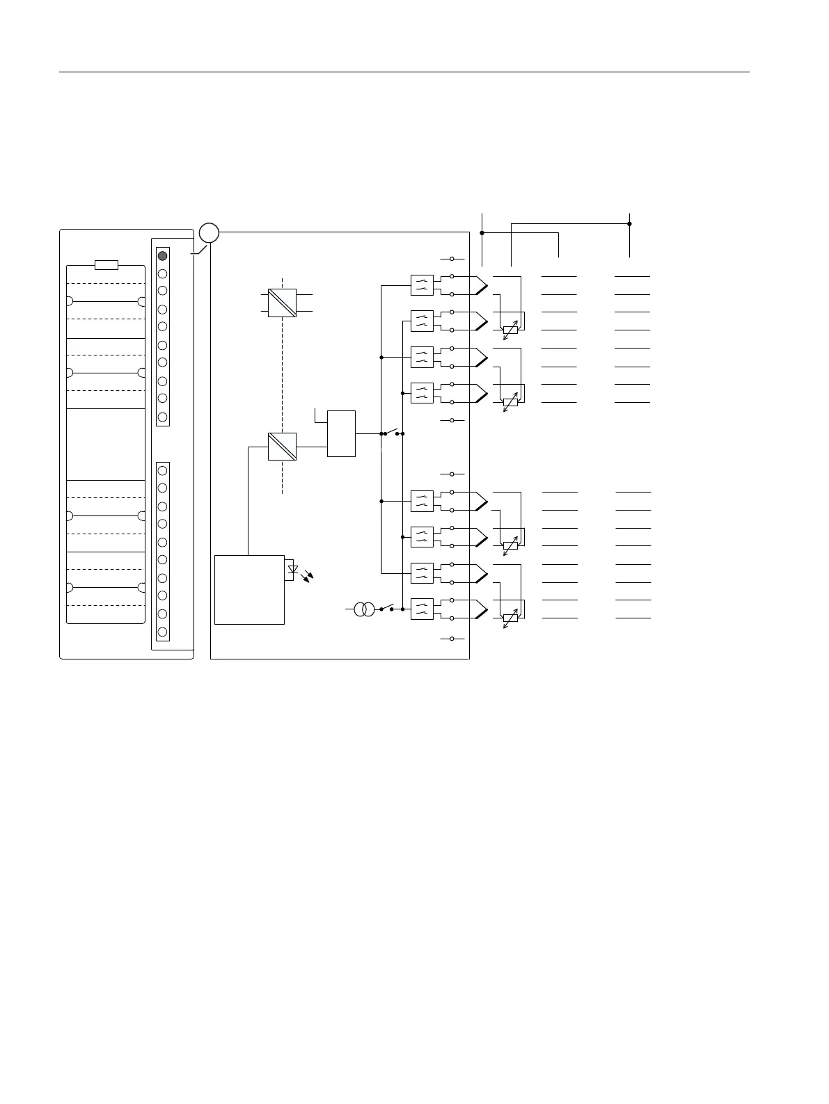
Wiring and block diagrams of the AI 8 x TC/4 x RTD
Module view and wiring diagram of AI 8 x TC/4 x RTD.
0
0
0
0
$'8
6)
&+
0
&+
0
,
&
&+
0
,
&
0
&+
0
&+
0
0
0
&+
,
&
,
&
0
0
0
&+
0
&+
0
,
&
&+
0
,
&
0
&+
0
&+
0
0
0
&+
,
&
0
,
&
6)
9LQWHUQDO
0LQWHUQDO
Electrical isolation
+ Input 0/0
- Input 0/0
+ Input 1/-
- Input 1/-
+ Input 2/2
- Input 2/2
+ Input 3/-
- Input 3/-
+ Input 4/4
- Input 4/4
+ Input 5/-
- Input 5/-
+ Input 6/6
- Input 6/6
+ Input 7/-
- Input 7/-
Internal supply
Internal
compensation
Thermocouples,
voltage measurement
Resistance
measurement
Opto-
multiplexer
Electrical isolation
Current
source
Logic and
backplane bus
interface
①Group error display - red (SF LED)
Figure 10-13 Module view and block diagram of the AI 8 x TC/4 x RTD
Notes on the module
No external supply voltage L+ (24 V) is necessary for the analog input module AI 8 x TC/4 x
RTD.
If thermal resistors (e.g. Pt100) are used for external compensation, connect them to channels
6 and 7.
If a compensation box is used for external compensation, connect it to channel 7.
Notes on the front connector
If you use the front connector 6ES7392-1AJ20-0AA0, you attain a higher accuracy of
temperature measurements with thermocouples in the "Internal compensation" measurement
type. The accuracy of the internal reference junction temperature is ± 1.5 K when this front
connector is used at ambient temperatures from 0 to 60 °C.
ET 200PA SMART I/O modules
10.4 Analog input modules
ET 200PA SMART
188 Operating Instructions, 06/2019, A5E34192013-AB
 Loading...


