Interrupts/diagnostic alarms
13.1 Status and error display
Analog input module AI Energy Meter 480VAC ST (6ES7134-6PA20-0BD0)
86 Manual, 12/2015, A5E36061895-AA
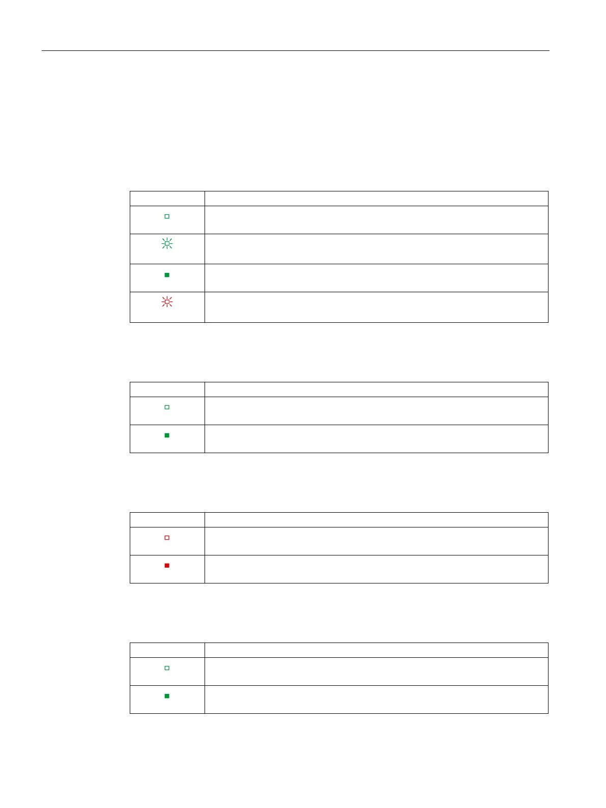
Meaning of the LED displays
The following table explains the meaning of the status and error displays. Remedial
measures for diagnostic alarms can be found in the section Diagnostic alarms (Page 88).
Table 13- 1 Meaning of the DIAG LED
Supply voltage of the ET 200SP not OK
Module not ready for operation (no parameters assigned)
On
Module parameters assigned and no module diagnostics
Module parameters assigned and module diagnostics
Table 13- 2 Meaning of the Status LED
Channel deactivated or error
Channel activated and no error
Table 13- 3 Meaning of the Error LED
Table 13- 4 Meaning of the PWR LED