Mounting and connecting the device
3.3 Connecting the device
Comfort Panels
48 Operating Instructions, 08/2018, A5E36770603-AC
Connecting the power supply
Safe electrical isolation
For the 24 V DC supply, use only power supply units with safe electrical isolation in
accordance with IEC 60364-4-41 or HD 384.04.41 (VDE 0100, Part 410), e.g. conforming
to the SELV/PELV standard.
The supply voltage must be within the specified voltage range. Otherwise, malfunctions at
the HMI device cannot be ruled out.
Applies to non-isolated system configurations:
Connect the GND 24 V connection from the 24 V power supply output to equipotential
bonding for uniform reference potential. You should always select a central point of
termination.
External protective circuit
An external protective circuit is required for operation with 24 V DC, see section 7
"Lightning protection and overvoltage protection" in function manual "Designing
interference-free controllers
(https://support.industry.siemens.com/cs/ww/en/view/59193566
)".
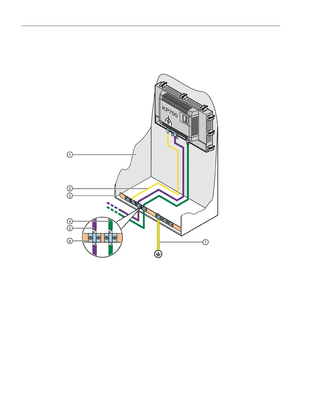
The following figure shows the connection between the power supply and the HMI device
with TP1500 Comfort V2 as an example.
The power supply connector is contained in the accessory kit. The power supply connector is
designed for cables with a maximum cross-section of 1.5 mm².
Additional information on the supplied power supply connectors and additional permitted
power supply connectors can be found in the section "Accessories (Page 22)."