EasyManua.ls Logo

Siemens SIMOTICS S-1FL6

Siemens SIMOTICS S-1FL6
432 pages
To Next Page IconTo Next Page
To Previous Page IconTo Previous Page
Loading...
Connecting
4.5 Encoder interface - X9
SINAMICS V90, SIMOTICS S-1FL6
Operating Instructions, 04/2019, A5E36037884-007
165
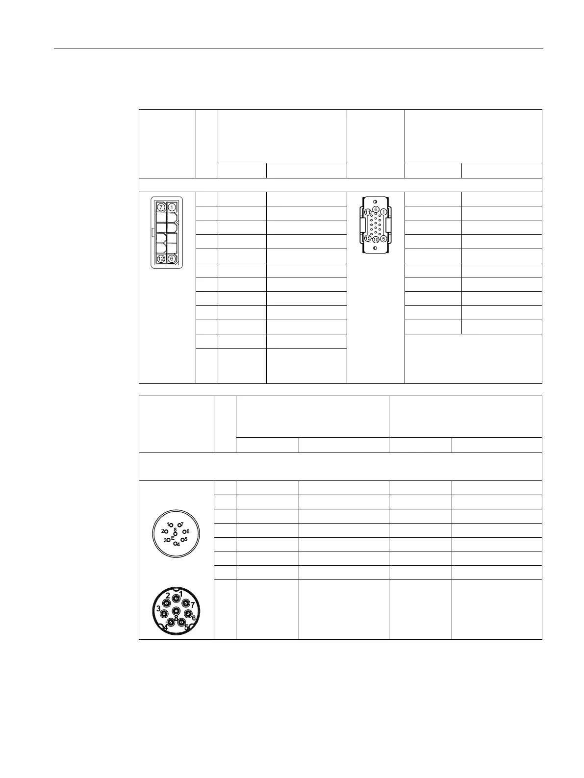
Encoder connector - motor side
Illustration
Pin
Incremental encoder TTL 2500
ppr
Illustration
Absolute encoder single-turn 21-
bit
Absolute encoder 20-bit + 12-bit
multi-turn
Signal
Description
Signal
Description
Low inertia motor, shaft-height: 20 mm, 30 mm and 40 mm
1
P_Supply
Power supply 5 V
P_Supply
Power supply 5 V
2 M Power supply 0 V M Power supply 0 V
3
A+
Phase A+
Clock_P
Clock
4
B+
Phase B+
Data_P
Data
5
R+
Phase R+
n. c.
Not connected
6
n. c.
Not connected
P_Supply
Power supply 5 V
7
P_Supply
Power supply 5 V
M
Power supply 0 V
8
M
Power supply 0 V
Clock_N
Inverted clock
9
A-
Phase A-
Data_N
Inverted data
10
B-
Phase B-
Shielding
Grounding
11
R-
Phase R-
Note
The pin11 to pin15 of the abso-
lute encoder connector are not
connected.
12 Shielding Grounding
Illustration
Pin
Incremental encoder TTL 2500 ppr
Absolute encoder single-turn 21-bit
Absolute encoder 20-bit + 12-bit
multi-turn
Signal
Description
Signal
Description
Low inertia motor, shaft-height: 50 mm
High inertia motor, shaft-height: 45 mm, 65 mm, and 90 mm
Straight con-
nectors:
Angular con-
nectors:
1
P_Supply
Power supply 5 V
P_Supply
Power supply 5 V
2
M
Power supply 0 V
M
Power supply 0 V
3
A+
Phase A+
n. c.
Not connected
4 A- Phase A- Clock_N Inverted clock
5
B+
Phase B+
Data_P
Data
6
B-
Phase B-
Clock_P
Clock
7
R+
Phase R+
n. c.
Not connected
8 R- Phase R- Data_N Inverted data

Table of Contents

Other manuals for Siemens SIMOTICS S-1FL6

Related product manuals