)',LQSXWVLJQDOV
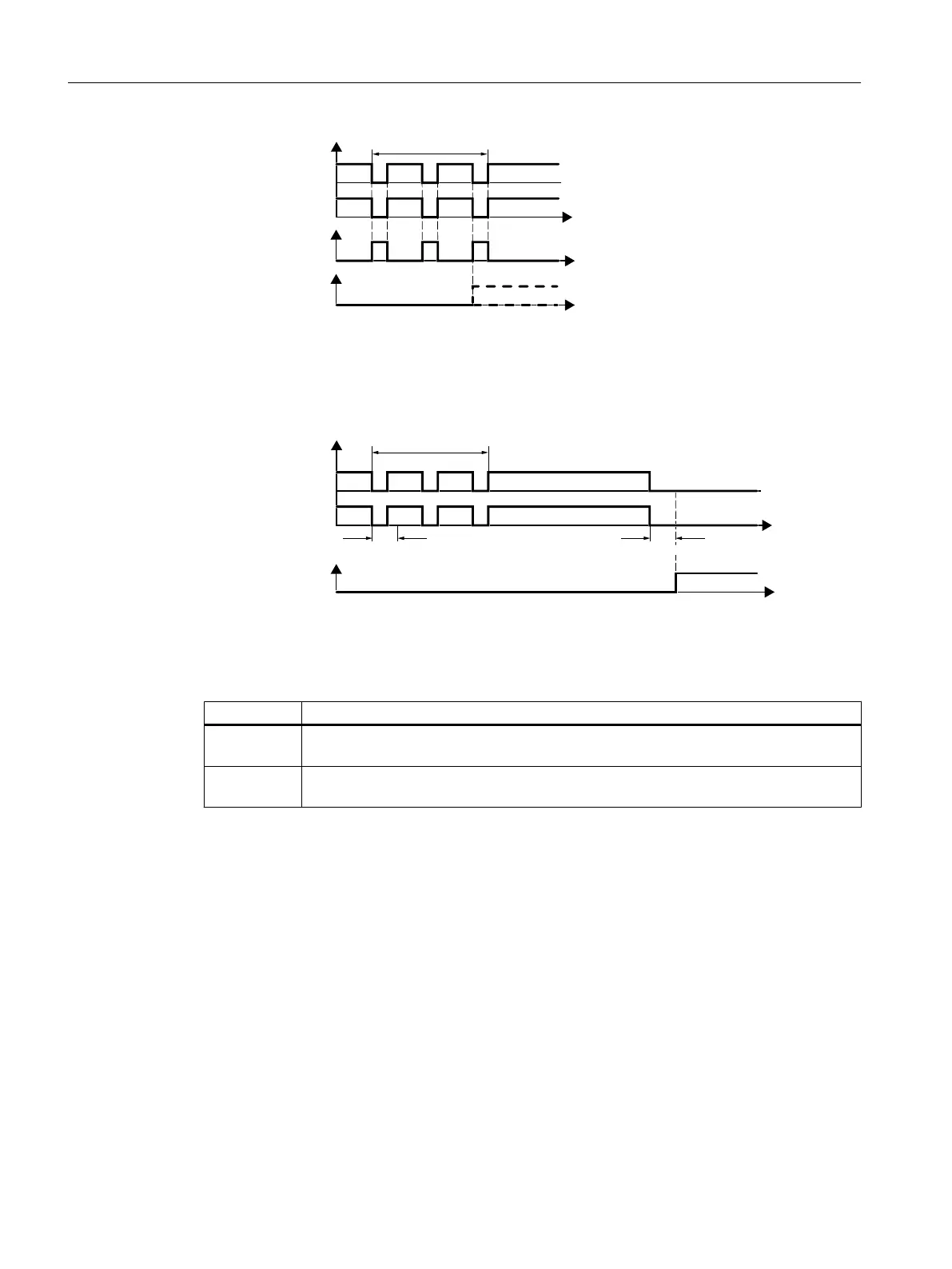
6DIHW\IXQFWLRQDFWLYH
)DXOW)
%LWSDWWHUQWHVW
W
W
W
Figure 5-5 Inverter response to a bit pattern test
A filter in the inverter suppresses brief signals as a result of the bit pattern test or contact
bounce.
)',LQSXWVLJQDOV
6DIHW\IXQFWLRQDFWLYH
'HERXQFHWLPH
%LWSDWWHUQWHVW
'HERXQFHWLPH
W
W
Figure 5-6 Filter to suppress brief signals
The filter extends the response time of the safety function by the debounce time.
Parameter Description
p9650
1)
F-DI switchover discrepancy time (factory setting: 500 ms)
Tolerance time to change over the fail-safe digital input for the basic functions.
p9651 STO debounce time (factory setting: 1 ms)
Debounce time of the fail-safe digital input for the basic functions.
1)
For SIMATIC ET 200pro FC-2, the tolerance time is always 0 ms.
Debounce times for standard and safety functions
The debounce time p0724 for "standard" digital inputs has no influence on the fail-safe digital
input signals. Conversely, the same applies: The debounce time of the fail-safe digital inputs
does not affect the signals of the "standard" inputs.
If you use an input as a standard input, set the debounce time using parameter p0724.
If you use an input as a fail-safe digital input, set the debounce time as described above.
Commissioning
5.11 Setting basic functions
Safety Integrated - SINAMICS G110M, G120, G120C, G120D and SIMATIC ET 200pro FC-2
130 Function Manual, 01/2017, FW V4.7 SP6, A5E34261271B AD

 Loading...


