4.4.3.1 Electromechanical sensor
Connecting an electromechanical sensor
9RXW
672B$
672B%
9
9
9
9
*1'
672B$
672B%
9
9
9
9
9'&0
6,1$0,&6*
3RZHU0RGXOH30
303
6,1$0,&6*
3RZHU0RGXOH30
303
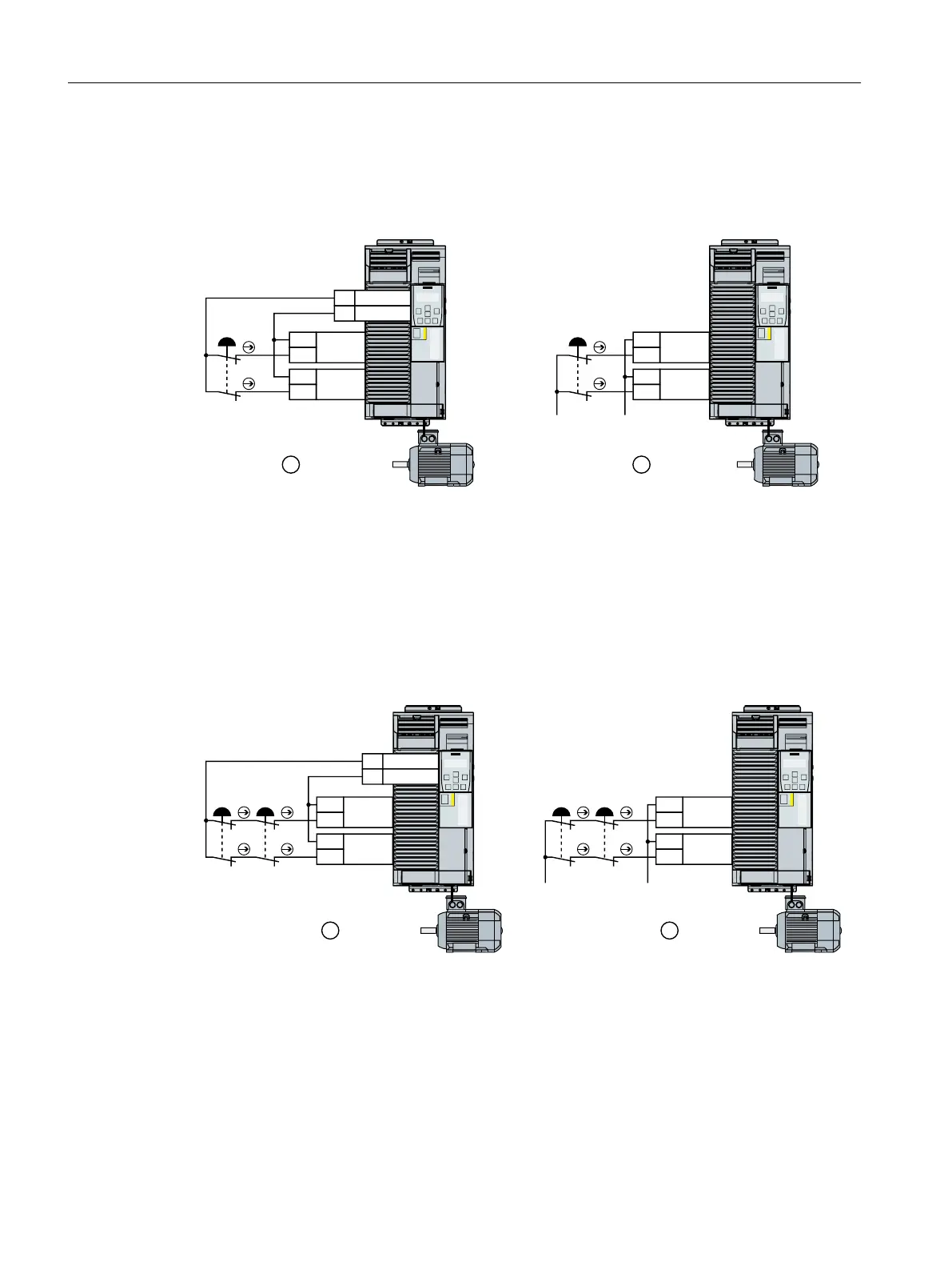
① Power supply voltage from terminal 9 of the Control Unit
② External power supply
Figure 4-31 Connecting an electromechanical sensor
If there is a risk of cross-circuits or short-circuits, the cables between the sensor and the inverter
must be protected, for example, by routing them in a steel tube.
Connecting several electromechanical sensors in series
9RXW
672B$
672B%
9
9
9
9
*1'
672B$
672B%
9
9
9
9
9'&0
6,1$0,&6*
3RZHU0RGXOH30
303
6,1$0,&6*
3RZHU0RGXOH30
303
① The inverter provides the supply voltage
② External power supply
Figure 4-32 Connecting several electromechanical sensors in series
You can connect electromechanical sensors, for example, Emergency Stop command devices,
position switches in series.
Installing
4.4 Controlling via a fail-safe digital input
Safety Integrated - SINAMICS G110M, G120, G120C, G120D and SIMATIC ET 200pro FC-2
84 Function Manual, 01/2017, FW V4.7 SP6, A5E34261271B AD

 Loading...


