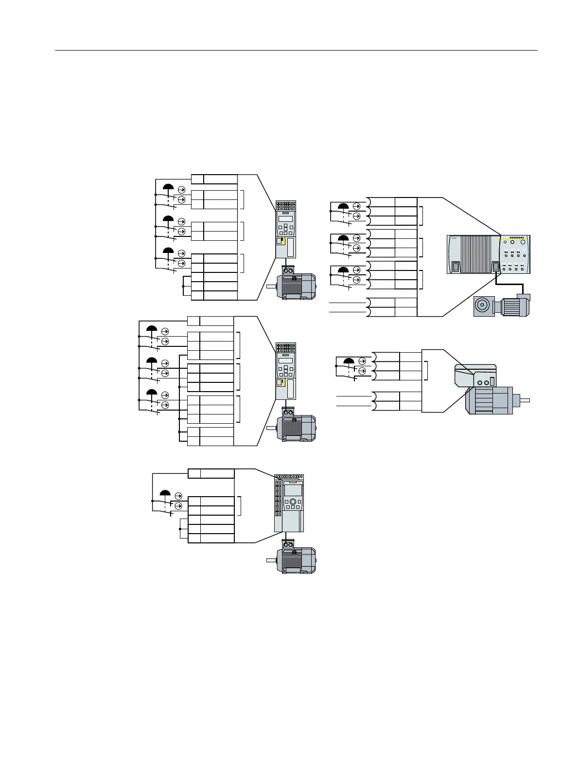
4.4.2.1 Electromechanical sensor
If there is a risk of cross-circuits or short-circuits, the cables between the sensor and the inverter
must be protected, for example, by routing them in a steel tube.
The inverter supplies the power supply voltage
)',
)',
)',
',
9RXW
',
',
',
',
',
',&20
',&20
*1'
)',
9RXW
',
',
',&20
',&20
*1'
6,1$0,&6*
&8(
)',
)',
)',
',
9RXW
',
',
',
',
',
',
',
',
',&20
*1'
6,1$0,&6*
&86
6,1$0,&6
*&
9'&
0
)',
)',
)',
;
',
;
/
;
',
;',
;/
;',
;',
;
/
;',
;
0
;/
6,1$0,&6
*'
9'&
0
)',
;',
;/
;',
;0
;/
6,1$0,&6
*0
1)
The 24 V supply is not required when using the G110M option "24 V power supply", article number
6SL3555-0PV00-0AA0
Figure 4-7 Connecting an electromechanical sensor to the inverter power supply
Installing
4.4 Controlling via a fail-safe digital input
Safety Integrated - SINAMICS G110M, G120, G120C, G120D and SIMATIC ET 200pro FC-2
Function Manual, 01/2017, FW V4.7 SP6, A5E34261271B AD 63

 Loading...


