Status
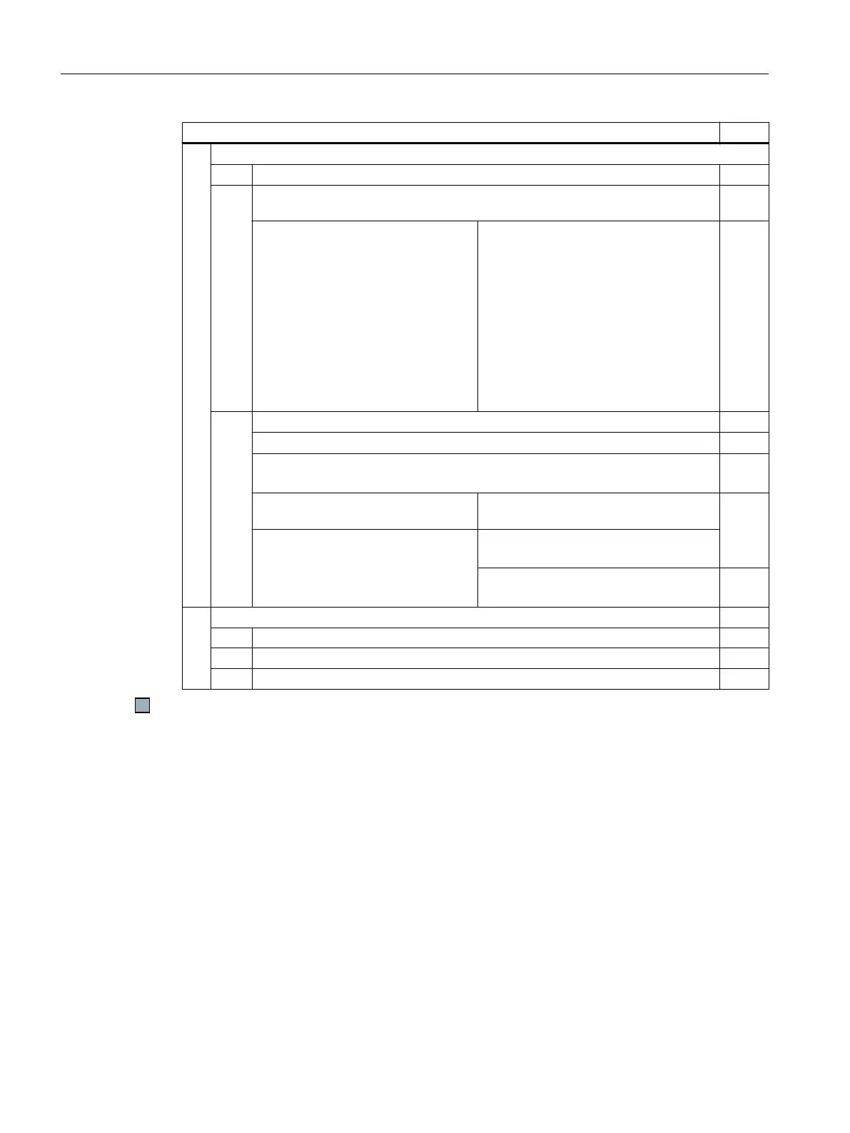
4. Test the set limit value
4.1. Enter a negative speed setpoint.
4.2.
The following test depends on how you have set the SDI function during commis‐
sioning:
STOP A in the event of a limit value
violation
● The inverter signals the following:
– C01716 and C30716
(tolerance for safe direction of
motion exceeded)
– C01700 and C30700 (STOP A
initiated)
STOP B in the event of a limit value vio‐
lation
● The inverter signals the following:
– C01716 and C30716 (tolerance
for safe direction of motion
exceeded)
– C01701 and C30701 (STOP B
initiated)
– C01700 and C30700 (STOP A
initiated)
4.3. Analyze the trace:
● When SDI+ is selected, the inverter signals: SDI+ is active (r9722.12 = 1).
● If r9713[0] > SDI tolerance, then the inverter signals an internal event
(r9722.7 = 0).
STOP A in the event of a limit value
violation
STOP B in the event of a limit value vio‐
lation
● The motor coasts down to a
standstill (r9722.0 = 1).
● The inverter brakes the motor on the
OFF3 ramp (r9722.1 = 1).
● After braking, STO is active
(r9722.0 = 1).
5. Acknowledge fault
5.1. Deselect SDI+.
5.2. Check: SDI+ is not active (r9722.12 = 0).
5.3. Acknowledge the messages for the safety functions.
You have completed the acceptance test of the SDI function for the positive direction of rotation.
Appendix
A.2 Examples of acceptance tests
Safety Integrated - SINAMICS G110M, G120, G120C, G120D and SIMATIC ET 200pro FC-2
406 Function Manual, 01/2017, FW V4.7 SP6, A5E34261271B AD

 Loading...


