5
03.04 "Parameters" Operating Area
5.1 Tool data
5
Siemens AG, 2004. All rights reserved
SINUMERIK 840D/840Di/810D Operator's Guide HMI Advanced (BAD) – 03.04 Edition 5-171
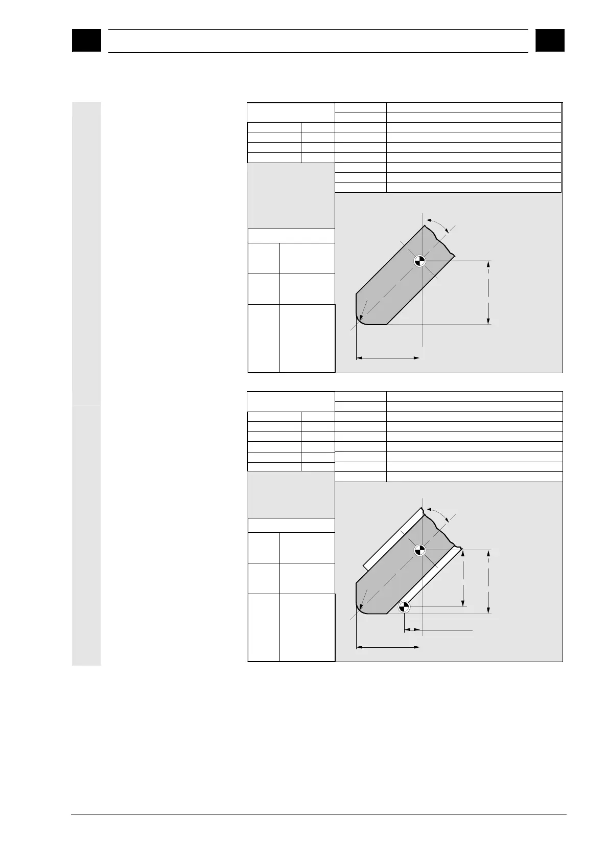
Required offset values
for inclined grinding
wheel with implicit
monitoring selection
F'
Entries in
tool parameters
STC_DP1
STC_DP3
STC_DP4
STC_DP6
403
Length 1
Length 2
Radius
STC_TPG1
STC_TPG2
STC_TPG4
STC_TPG5
STC_TPG6
STC_TPG7
STC_TPG8
STC_TPG3
STC_TPG9
Spindle number
Chaining rule
Minimum wheel radius
Minimum wheel width
Current wheel width
Maximum speed
Max. surface speed
Angle of the inclined wheel
Parameter no. for radius calculation
Wear values according
to requirement
Other values must
be set to zero
Effect
G17:
G18:
G19:
Length 1 in Y
Length 2 in X
Radius in X/Y
Length 1 in X
Length 2 in Z
Radius in Z/X
Length 1 in Z
Length 2 in Y
Radius in Y/Z
F: Toolholder reference point
Radius
Length 2 (Z)
∝
Length
1 (X)
Required offset values
using the example of
inclined grinding wheel
with implicit monitoring
selection
F'
F
Entries in
tool parameters
STC_DP1
STC_DP3
STC_DP4
STC_DP6
403
Length 1
Length 2
Radius
STC_TPG1
STC_TPG2
STC_TPG4
STC_TPG5
STC_TPG6
STC_TPG7
STC_TPG8
STC_TPG3
STC_TPG9
Spindle number
Chaining rule
Minimum wheel radius
Minimum wheel width
Current wheel width
Maximum speed
Max. surface speed
Angle of the inclined wheel
Parameter no. for radius calculation
Wear values according
to requirement
Other values must
be set to zero
Effect
G17:
G18:
G19:
Length 1 in Y
Length 2 in X
Radius in X/Y
Length 1 in X
Length 2 in Z
Radius in Z/X
Length 1 in Z
Length 2 in Y
Radius in Y/Z
F: Toolholder reference point
Radius
Geometry
Length 2
Base Length 2
Base
Length
1
Geometry
Length
1
∝