5
"Parameters" Operating Area 03.04
5.1 Tool data
5
Ó Siemens AG, 2004. All rights reserved
5-174 SINUMERIK 840D/840Di/810D Operator's Guide HMI Advanced (BAD) – 03.04 Edition
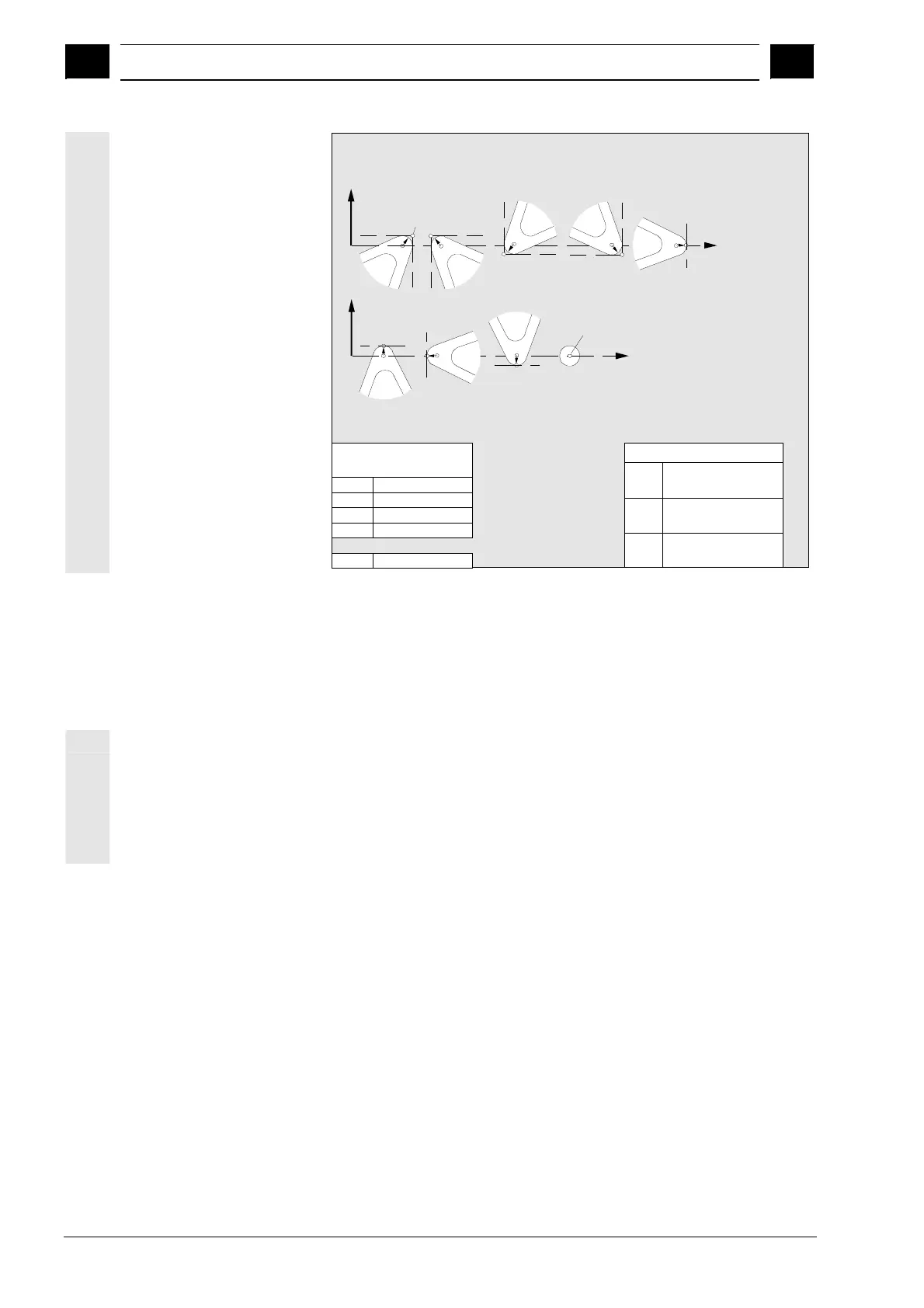
Required offset values
for a turning tool with
tool radius
compensation
Z
X
1
2
4
5
P
Z
X
76
8
9
P=S
3
Entries in
tool parameters
DP1
DP2
DP3
DP4
DP6
5xy
1...9
Length 1
Length 2
Radius
Effect
G17:
G18:
G19:
Length 1 in Y
Length 2 in X
Length 1 in X
Length 2 in Z
Length 1 in Z
Length 2 in Y
Wear values
according to
requirement
Other values must
be set to zero
Tool parameter DP2 defines the tool nose position.
Any value between 1 and 9 can be entered.
Tool nose position DP2
Note:
Length 1, length 2 refer to point P for edge
positions 1–8;
but in case of 9 to S (S = P)
· Group type 7xy (special tools)
700 Slotting saw
710 3D probe
711 Edge probe
730 Fixed stop

 Loading...


