05.91 8 Contour Definition
8.2 Contour definition programming
8.2 Contour definition programming
The elements described are valid for a turning machine with an operating area behind the
turning centre and for a milling machine in the selected plane Z-X (G18).
Examples 1 to 8 represent the basic elements of contour definition programming. These
contour elements can be combined in a number of ways. The addresses for the angle (in this
case A) and the radius (in this case B) are freely selectable in the control. The addresses must
not be allocated more than once.
A
2
A
1
X
3
, Z
3
X
2
or Z
2
I
X
2
or Z
2
A
X
Z
X
K
Z
X
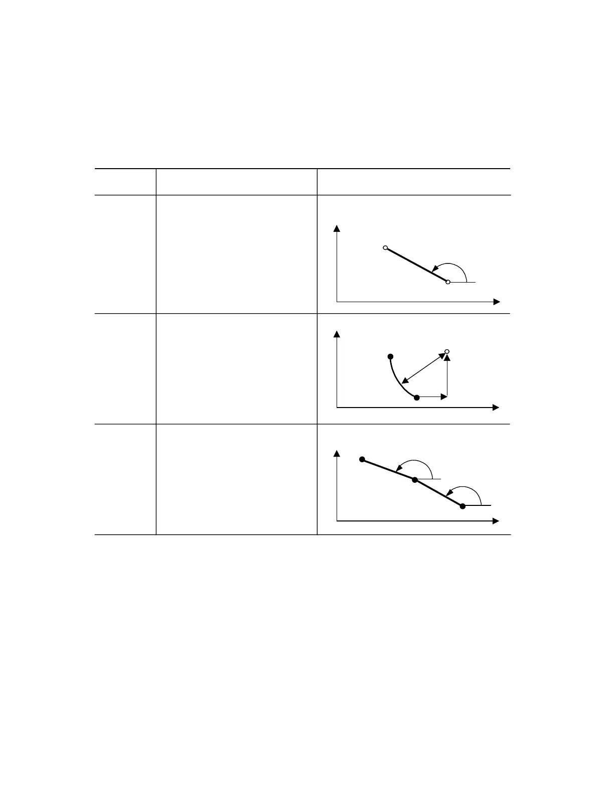
(1)
2-point definition
N... A... X
2
... (or Z
2
)
L
F
The second end coordinate is calculated by the
control.
(2)
Circular arc
N...G02 (or G03) I.. K.. B.. X
2
.. (or Z
2
)
L
F
The circular arc is limited to one quadrant.
The second end position coordinate is calculated
by the control. In the contour definitions
parameters I and K must both be programmed,
even if one of the values is zero.
(3)
3-point definition
N.. A
1
.. A
2
.. X
3
.. Z
3
..
L
F
The control calculates the coordinates of the
vertex and generates 2 blocks. Angle A2 is
referred to the second straight line.
Function Programming Example
B
Z
© Siemens AG 1991 All Rights Reserved 6ZB5 410-0HD02 8–3
SINUMERIK 880, (PG)
 Loading...


