05.91 9 Tool Offsets
9.8 Tool offsets for angle cutter
9.8 Tool offsets for angle cutter
As opposed to the end mill, an angle cutter requires an additional length compensation located
in the plane of the cutter radius compensation. Free axis selection must always be used with
preparatory function G16.
Function G16 is followed in this instance by four axis addresses:
1st and 2nd axis address: Plane in which the cutter radius compensation is to be active
3rd axis address: Standard length compensation as in the case of the end mill
4th axis address: Additional length compensation in the cutter radius plane.
The third and fourth axis addresses can be given a negative sign to reverse the direction of
compensation.
The number “30” must be entered under P1 (tool type).
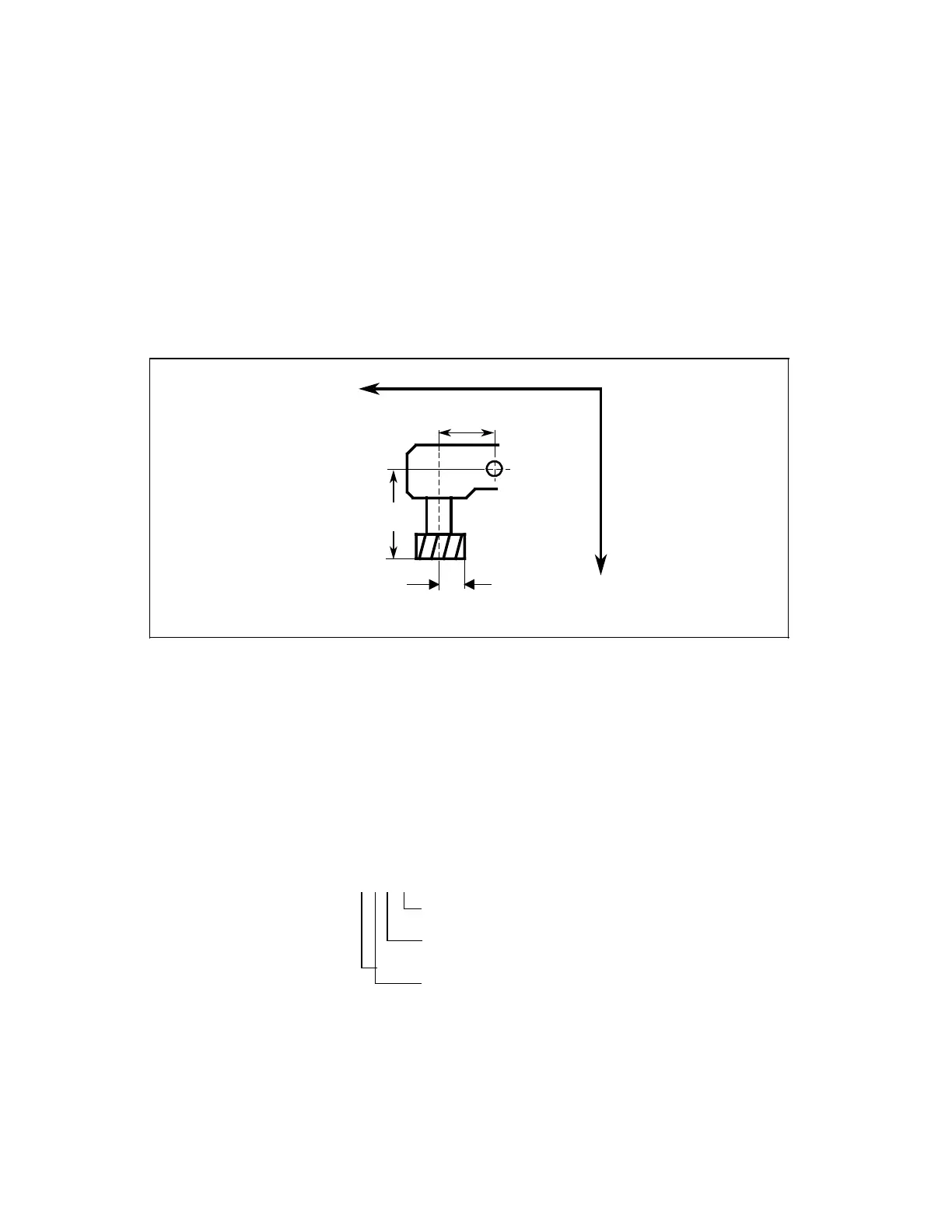
Length 2
X
Z
Radius
Length 1
P1 : Tool type (enter:30)
P2 : Geometry, length 1
P3 : Geometry, length 2
P4 : Geometry, cutter radius
P5 : Wear, length 1
P6 : Wear, length 2
P7 : Wear, cutter radius
Compensation
assignments: G16 X Y Z X
Geometry length 2 (additional length compensation)
Geometry length 1 (standard length compensation
as in the case of end mill)
Plane, in which the cutter radius compensation is to
be active
© Siemens AG 1991 All Rights Reserved 6ZB5 410-0HD02 9–13
SINUMERIK 880, (PG)
 Loading...


