05.91 4 Programming of Motion Blocks
4.2.2 Circular interpolation G02/G03
4.2.2 Circular interpolation G02/G03
The tool must travel between two points on the contour in a circular arc while simultaneously
machining the workpiece.
The control calculates the traversing path by means of circular interpolation.
Circular interpolation effects tool motion relative to the workpiece
• along a circular arc
in a clockwise direction with G02,
in a counterclockwise direction with G03,
• around the programmed centre point of the circle,
• from the starting position on a circular path to the programmed end position.
The action of the preparatory functions G02 and G03 is modal.
The direction of rotation of the circle is determined on the basis of a perpendicular coordinate
system. The axes involved in the circle represent the horizontal and the vertical axis.
If the circle is in the tool offset plane (G16 to G19), the direction of rotation is determined by
the defined plane. If the circle is not located in the tool offset plane, the written sequence of
the axis addresses applies:
1
st
programmed axis = horizontal axis (abscissa)
2
nd
programmed axis = perpendicular axis (ordinate)
If only one axis is programmed and this axis is located in the tool offset plane, the associated
second axis is supplemented automatically. If the axis is not located in the tool offset plane,
alarm 3006 (wrong block structure) is issued.
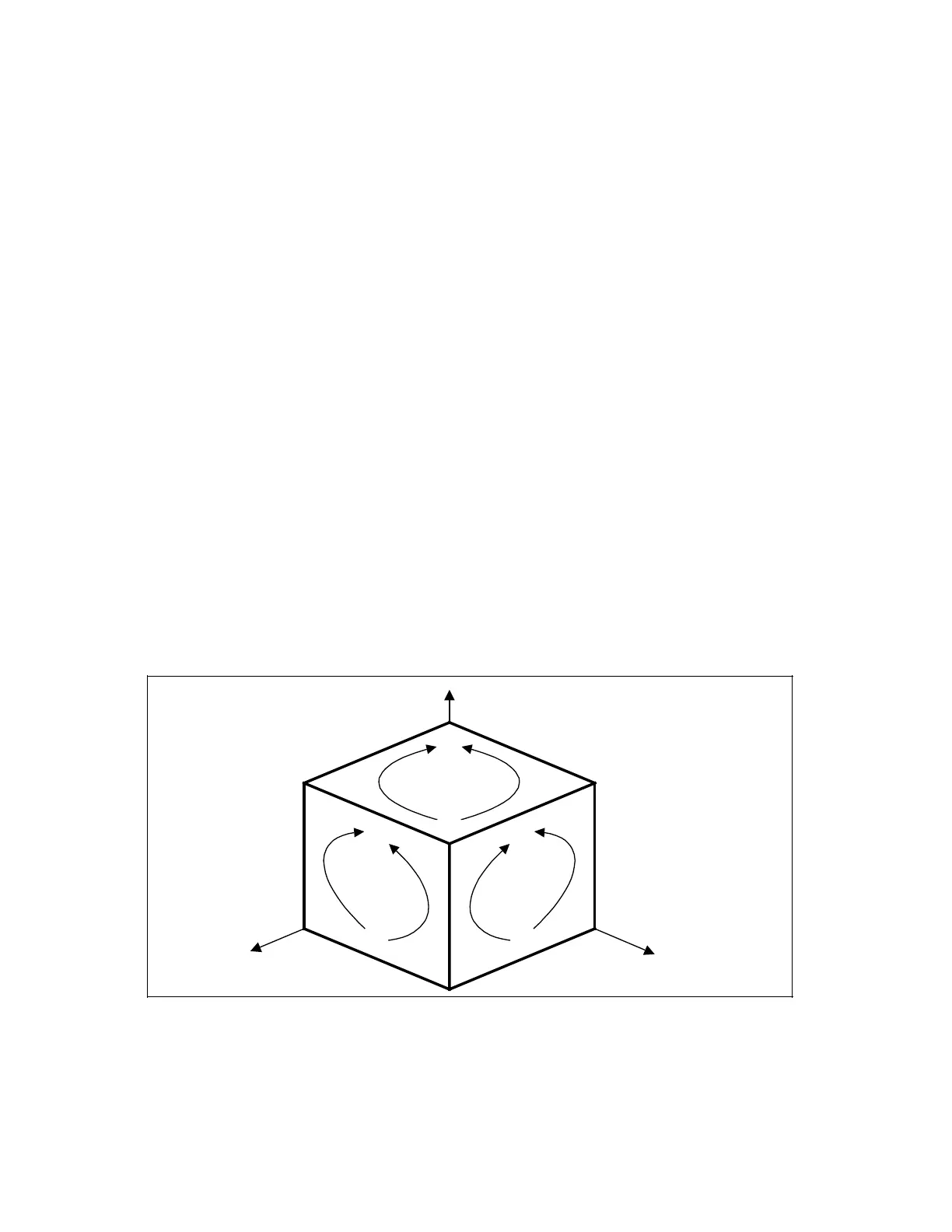
The direction of rotation in the various tool offset planes (G16 to G19) is defined as follows,
looking towards the axis perpendicular to the plane. The tool will move in a clockwise direction
with G02 or in a counter-clockwise direction with G03.
Circular interpolation
G02
G03
G02 G03
G19
G02
G03
Z
X
Y
G17
G18
© Siemens AG 1991 All Rights Reserved 6ZB5 410-0HD02 4–7
SINUMERIK 880, (PG)
 Loading...


