10 Cutter Radius Compensation (CRC), Tool Nose Radius Compensation (TNRC) 01.93
10.1 Selection of CRC/TNRC
Selection of compensation mode
Selection of compensation work while 90° 180° and while is < 90° not permitted.
10.2 CRC/TNRC in program
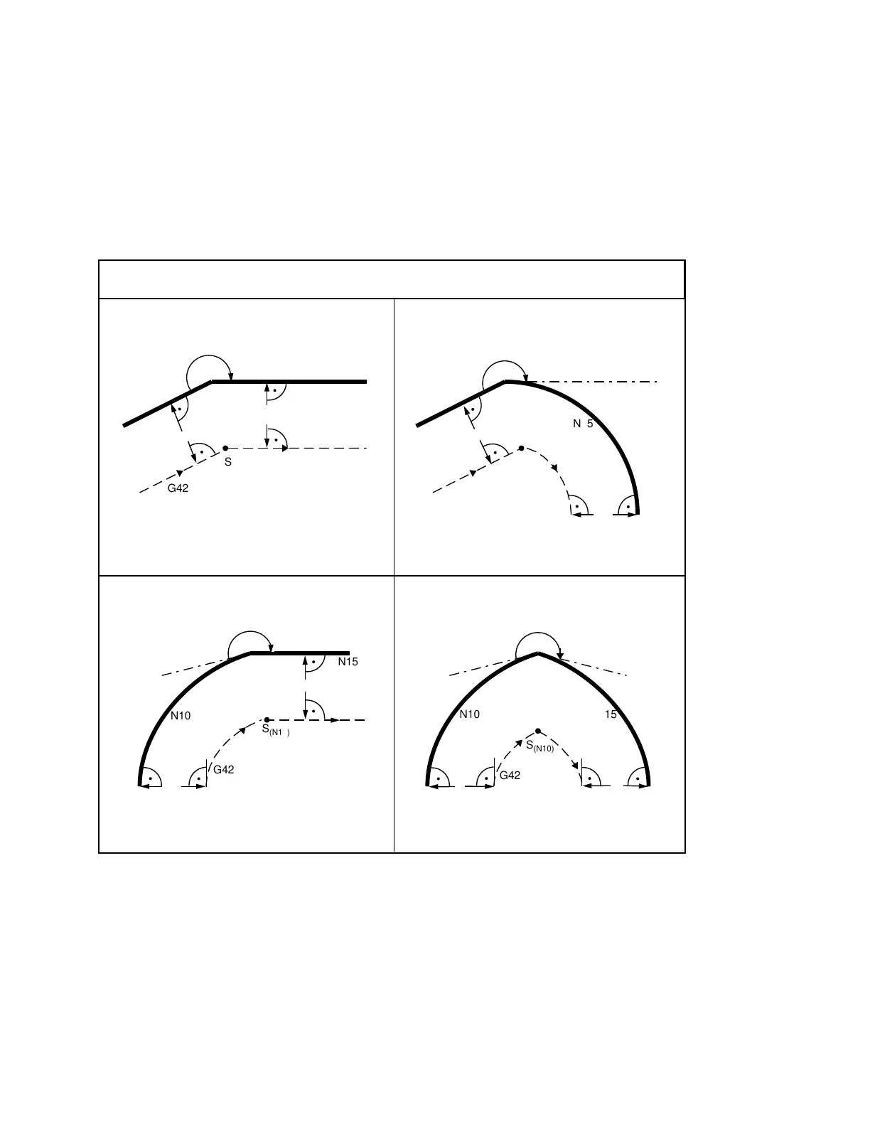
When CRC/TNRC is selected the control reads in two further blocks in advance during proces-
sing of the current block and calculates the intersection point of the compensated paths. The
diagrams below show compensation for various transitions.
Compensation mode for various transitions for
> 180°
N10
a
a
G42
N15
G42
S
(N10)
N15N10
N10
S
(N10)
G42
N15
S
(N10)
S
(N10)
N10
G42
N15
Straight line/straight line Straight line/circular arc
Circular arc/circular arcCircular arc/straight line
> 180°
R
R
R
R
R
R
R R
10–2 © Siemens AG 1991 All Rights Reserved 6ZB5 410-0HD02
SINUMERIK 880, (PG)
 Loading...


