05.91 4 Programming of Motion Blocks
4.2.5 Polar coordinates G10/G11/G12/G13/G110/G111
4.2.5 Polar coordinates G10/G11/G12/G13/G110/G111
Drawings dimensioned with angles and radii can be entered directly in the program with the aid
of the polar coordinates.
The following preparatory functions are available for programming with polar coordinates:
G10 Linear interpolation, rapid traverse
G11 Linear interpolation, feedrate (F)
G12 Circular interpolation, clockwise
G13 Circular interpolation, counter-clockwise
G110 Adopt programmed setpoint position as new centre point
G111 Polar coordinate programming with angles and radii.
The action of the preparatory functions is modal.
a
a
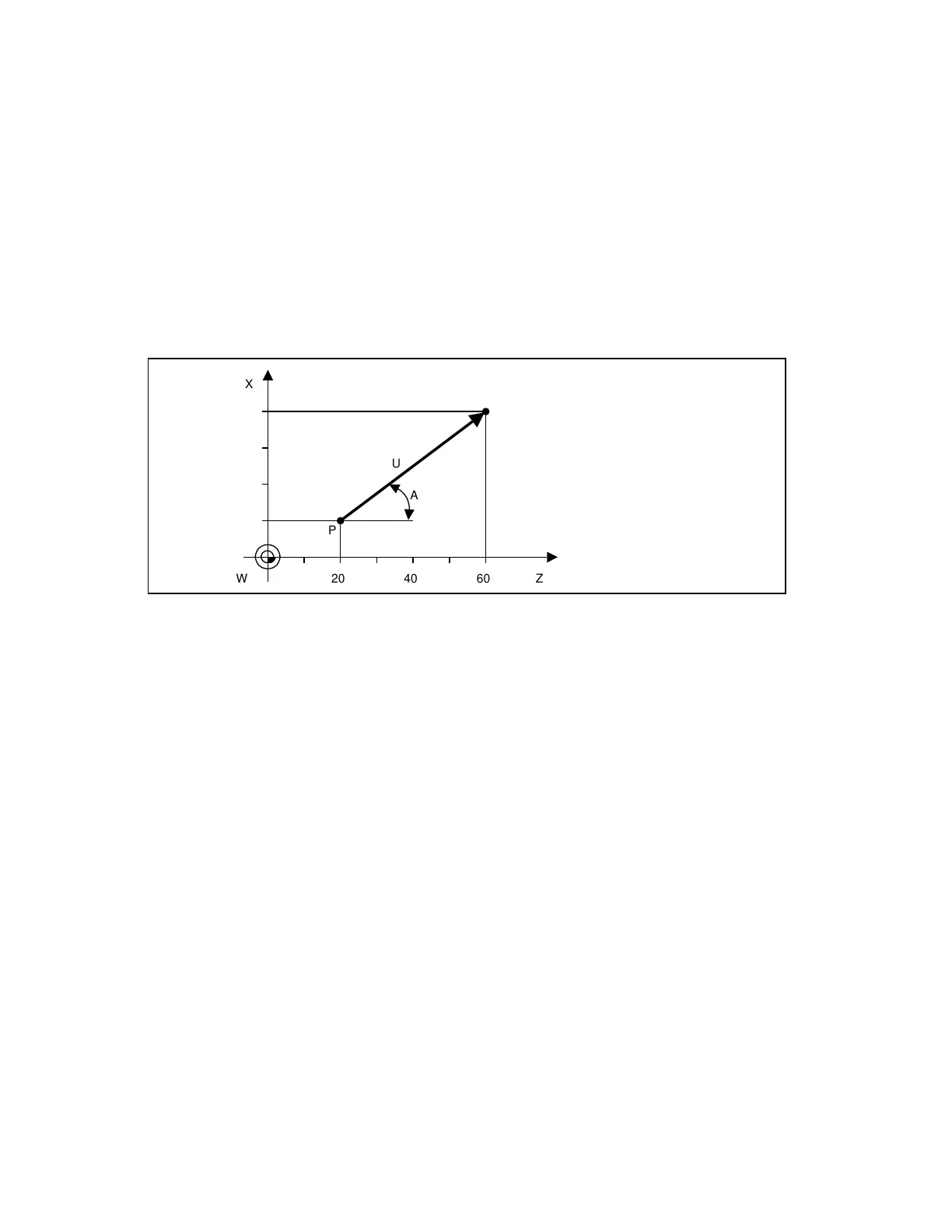
A
U
P
W Z604020
X
P2
20
10
30
40
W Workpiece zero
M Centre point of polar coordinate system
A Angle
U Radius
In order to determine the traverse path, the control requires the centre point, the radius and
the angle. The centre point is entered with perpendicular coordinates (X, Y, Z) and - on initial
programming - using absolute position data. A subsequent incremental position data input (with
G91) always refers to the last centre point programmed.
The action of the centre point entry is modal and can be reset by means of M02/M30.
The radius is programmed under the address B or U without sign. The angle is entered under
the address A (input resolution 10
-5
degrees). It always refers to the first positive axis of the
polar coordinates to be programmed (reference axis). The positive direction of this axis
corresponds to an angle of 0 degrees. Angles are specified as absolute or incremental and
positive or negative data.
© Siemens AG 1991 All Rights Reserved 6ZB5 410-0HD02 4–17
SINUMERIK 880, (PG)
 Loading...


