01.93 2 Fundamentals of Programming
2.9 Channel-specific programming
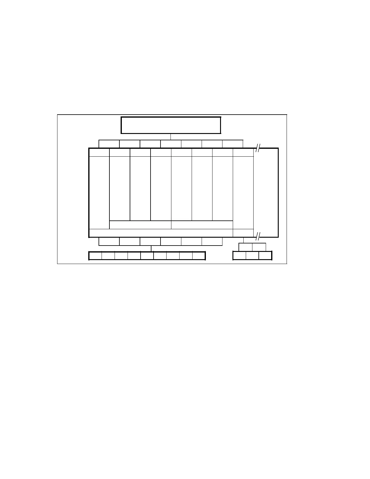
The machine units
• Slide 1, main spindle, auxiliary spindle
• Turret 1,
• Slide 2,
• Turret 2 and
• Loader
can be allocated to the channels of the SINUMERIK 880 according to the following scheme:
Channel structure: Programmable allocation of channels
Max.
16 chan-
nels with
SINU-
MERIK
880,
SW 6
Mode
group >
Axes/
spindles
Central
part program memory
1 2 3 4 5 6 7 8
X1
Z1
S1
C
S2
Turning
and
milling
T1
Turret
1
X2
Z2
(S1)
T2
Turret
2
Q1
Q2
Q3
Loader
Slide 1 Slide 2
1 2
X1 Z1 S1 C S2 T1 X2 Z2 T2 Q1 Q2 Q3
Channel
A mode group contains those channels that, due to the operational sequence, must always
work simultaneously in the same mode. Within the mode group, any axis can be programmed
in any channel. In the above example, the loader has been assigned an own mode group. This
assignment permits Setting-up operation of the loader while workpieces are being
produced.
In addition to the 5 channels in which the programs for controlling the working units are run, 3
channels are reserved to be able to include future add-ons such as automatic tool retraction
in the case of tool breakage or coordination programs.
In the AUTOMATIC basic display, each channel is given its program number.
The channel structure allows the programs of the various channels to be processed
simultaneously and asynchronously. If synchronization is required it can be performed via the
PLC.
In each mode group as many axes can be traversed simultaneously in Jog mode as there are
channels for the mode group.
© Siemens AG 1991 All Rights Reserved 6ZB5 410-0HD02 2–19
SINUMERIK 880, (PG)
 Loading...


