3 Directions of Movement, Dimensioning 01.93
3.7 Workpiece dimensioning, input system G70/G71
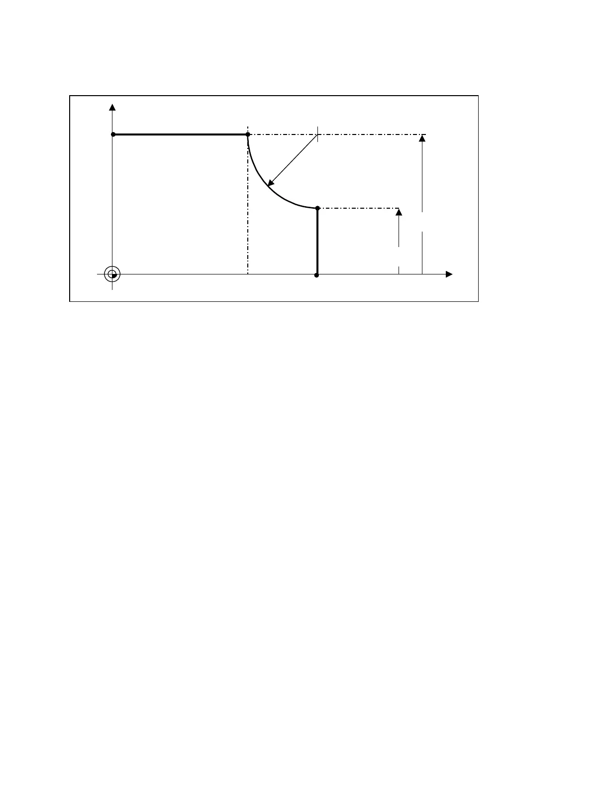
Example:
G71 - Initial setting (metric)
Input in inches initial setting G71
N15
N10
P4
P3
P2P1
W
N20
X
50 75.4 mm
mm
Z
B=1.”(Inch)”
60
110.8
N05 (shaft)
L
F
N10 G91 Z50.
L
F
(P2)
N15 G03 G70 X–1 Z1 K1 I0
L
F
(P3)
N20 G01 G71 X–30.
L
F
(P4)
N30
3–16 © Siemens AG 1991 All Rights Reserved 6ZB5 410-0HD02
SINUMERIK 880, (PG)
 Loading...


