Sr. no.
*)
Quan‐
tity
Name Note
⑤ 1 Pulley Installation with carrier pin ④ on lever ⑥
⑥ 1 Lever For the range of stroke from 3to 35mm
⑦ 2 U–bolts Only for actuators with columns
⑧ 4 Hexagon bolt M8x20 DIN933–A2
⑨ 2 Hexagon bolt M8x16 DIN933-A2, torque, section "Technical specications > Mechanical
construction (Page63)"
⑩ 6 Spring lock washer A8 - DIN127–A2
⑪ 6 Washer B8.4 - DIN125–A2
⑫ 2 Washer B6.4 - DIN125–A2
⑬ 1 Spring VD-115E 0.70 x 11.3 x 32.7 x 3.5
⑭ 1 Spring lock washer A6 - DIN137A–A2
⑮ 1 Lock washer 3.2 - DIN6799–A2
⑯ 3 Spring lock washer A6 - DIN127–A2
⑰ 3 cylinder head screw M6x25 DIN7984–A2
⑱ 1 Hexagon nut M6 - DIN934–A4
⑲ 1 Square nut M6 - DIN557–A4
⑳ 4 Hexagon nut M8 - DIN934–A4
*)
The numbers refer to the images of the description of the installation steps below.
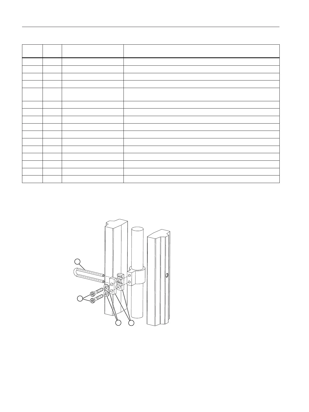
1. Install the clamping pieces ③ on the actuator spindle. Use spring lock washers ⑯ and
cylinder head screws ⑰ for this.
2. Slide the pick-up bracket ② into the milled recesses of the clamping pieces ③.
Figure4-2 Pick-up bracket
3. Tighten the screws ⑰ so that you can still shift the pick-up bracket ②.
Installing/mounting
4.2Mounting to linear actuator
SIPART PS100
22 Operating Instructions, 06/2023, A5E50188938-AF

 Loading...


