Behavior in case of failure of the electrical auxiliary power and/or the supply pressure PZ
(Page34)
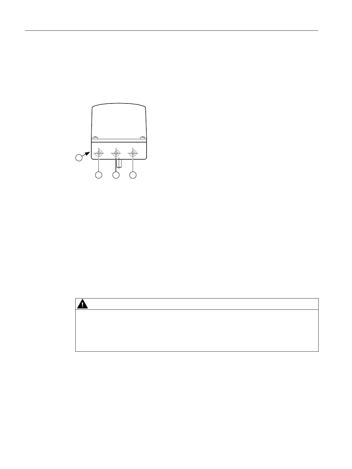
5.4.1 Structure of pneumatic connection
① Output: Actuating pressure Y2 *)
② Input: Supply pressure PZ
③ Output: Actuating pressure Y1
④ Exhaust air outlet with sound absorber, thread G¼
*) for double-acting actuators
Figure5-2 Pneumatic connection, example
5.4.2 Behavior in case of failure of the electrical auxiliary power and/or the
supply pressure PZ
Overview
CAUTION
Note the following before working on the control valve
Note that, before working on the control valve, you must rst move it to the safety position.
Make sure that the process valve has reached the safety position. If you only interrupt the
supply pressure PZ to the positioner, the safety position can in some cases only be attained after
a certain delay period.
The dierence between a failure of supply pressure PZ and a failure of electrical auxiliary
power:
• Failure of electrical auxiliary power means the failure of the signal source at the analog
input 4 to 20mA.
• Failure of the supply pressure PZ
Connecting
5.4Pneumatic connection
SIPART PS100
34 Operating Instructions, 06/2023, A5E50188938-AF

 Loading...


