9.2 Info IDs, error messages and corrective measures
The following table shows the IDs of diagnostic messages and possible causes and instructions
for corrective actions.
Messages on the local display
(Page37)
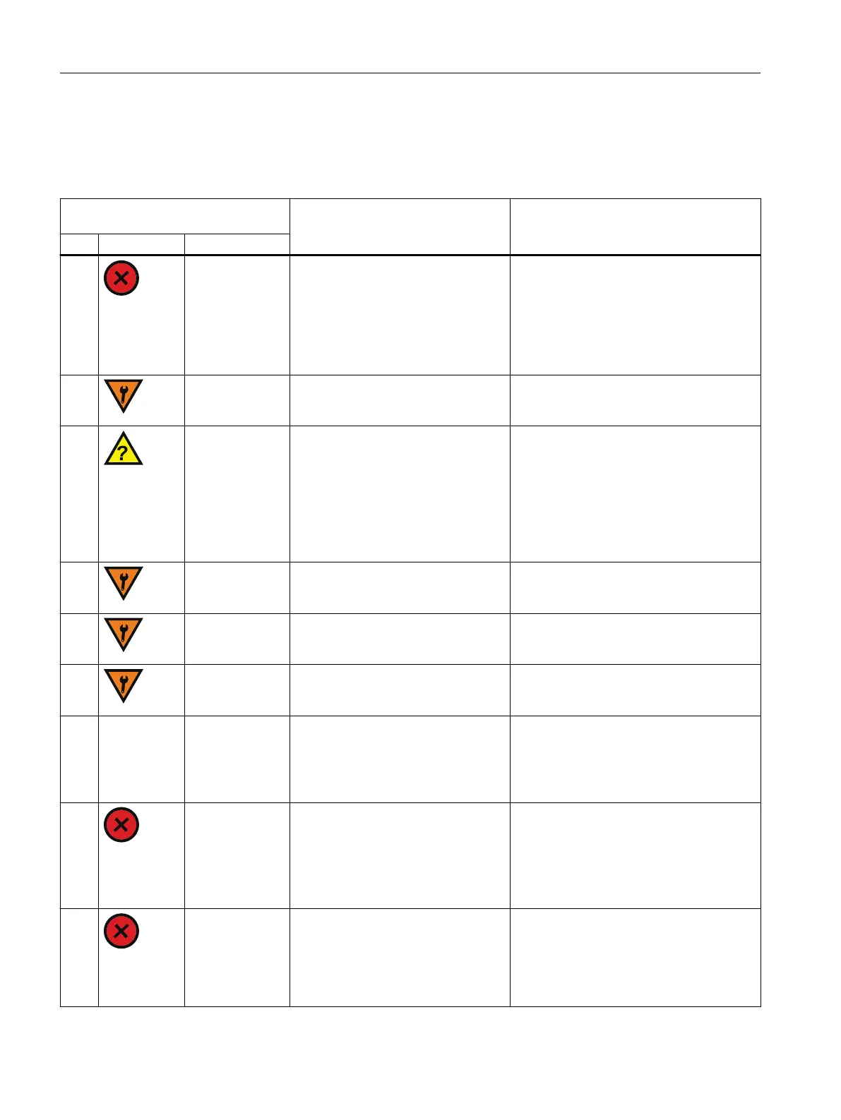
Meaning / cause
Remedy
ID Symbol Status line
6A NO MOVEMENT
• Errors during initialization
• Insucient supply of compressed
air
• Mounting kit not correctly moun‐
ted.
• Valve blocked
Eliminate the cause. Start the initialization
process.
6C NO INIT + set‐
point as percent‐
age
Positioner is not initialized Press left button to start the initialization of
the positioner.
6d -
• Measuring range of position de‐
tection exceeded
• Swivel area of the valve is larger
than 110°.
• Positioner installed on a dierent
actuator without re-initialization.
• End positions of valve are worn.
Check the mounting kit and the wear. Start
the initialization process.
6E DI-HOLD + set‐
point as percent‐
age
Maintain valve position is enabled
through digital input (DI).
Congured response. If required, adjust set‐
ting in parameter "DIGITAL IN" [01].
6F DI-GOCL + set‐
point as percent‐
age
Approach valve position is enabled
through digital input (DI).
Congured response. If required, adjust set‐
ting in parameter "CLOSE LIMIT" [05].
6H DI-GOOL + set‐
point as percent‐
age
Approach valve position is enabled
through digital input (DI).
Congured response. If required, adjust set‐
ting in parameter "OPEN LIMIT" [07].
6L - - Digital input (DI) is enabled. This sta‐
tus is reported via the digital output
(DO).
Setting in parameter "BEHAVIOR DI
[01] > MSG"
Not necessary.
6N SPAN TO HIGH
• Maximum angle span exceeded.
• Eective lever arm is not adjusted
to the actuator travel.
• Mounting kit not correctly moun‐
ted.
Position the carrier pin at a larger stroke val‐
ue.
Check the mounting kit.
Use the electropneumatic positioner SI‐
PART PS2 from Siemens with a swivel area of
185° (special design).
6P SPAN TO LOW
• Minimum angle span underrun.
• Eective lever arm is not adjusted
to the actuator travel.
• Mounting kit not correctly moun‐
ted.
Position the carrier pin at a smaller stroke
value.
Check the mounting kit.
Troubleshooting
9.2Info IDs, error messages and corrective measures
SIPART PS100
50 Operating Instructions, 06/2023, A5E50188938-AF

 Loading...


