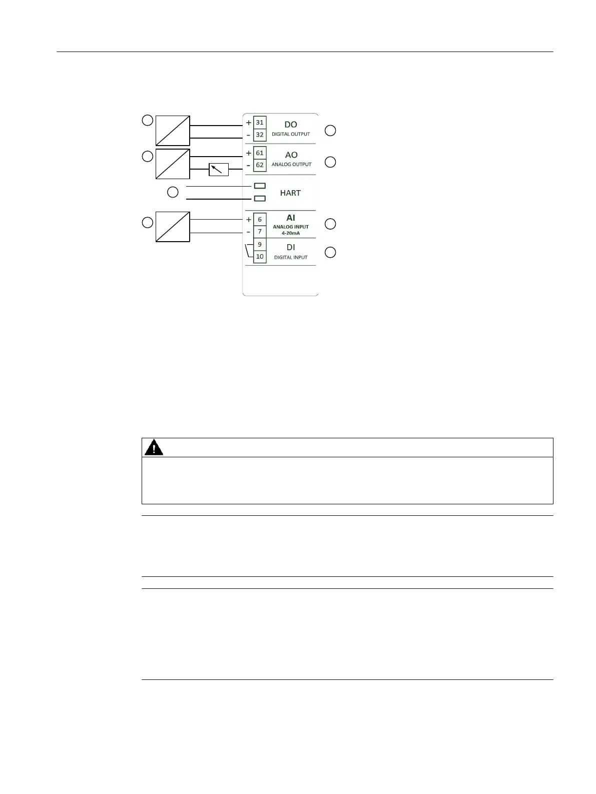
5.3 Electrical connection
① Digital input or switching amplier ⑤ Digital output
② Power source 12 to 30V DC ⑥ Analog output of position feedback
③ HART connector ⑦ Analog input current input 4 to 20mA
④ Signal source 4 to 20mA ⑧ Digital input (oating contact)
Figure5-1 Wiring diagram
5.4 Pneumatic connection
WARNING
Supply pressure PZ
For safety reasons, the supply pressure PZ can be fed after installation only if the positioner is
switched to the "NO INIT" mode when an electrical signal is available.
Note
Specications regarding air quality
Observe the specications regarding the air quality, see section "Technical specications
> Pneumatic data (Page63)".
Note
Leakage
Besides continuous air consumption, a leakage can cause the positioner to try to compensate
the position deviation. This will result in premature wear in the entire control device.
• Check if there is leakage with "LEAKAGE TEST".
• If there is leakage, check the pneumatic connections for leaks.
Structure of pneumatic connection (Page34)
Connecting
5.4Pneumatic connection
SIPART PS100
Operating Instructions, 06/2023, A5E50188938-AF 33
 Loading...


