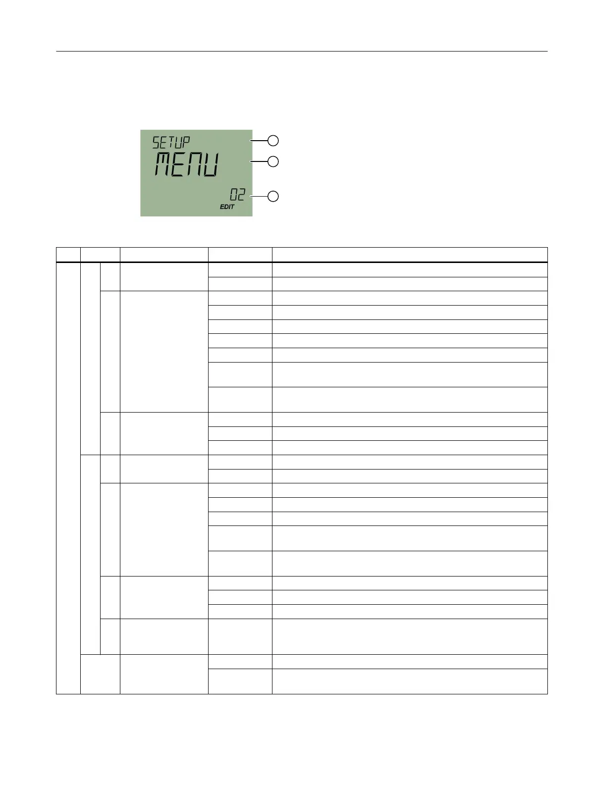
8.3 SETUP [02]
Setting the device parameters.
Factory-set parameter values are printed in bold in the table.
③ ① ② Meaning
01 DIGITAL IN Digital input (DI)
MENU Menu for setting the digital input (DI)
01
• BEHAVIOR DI
Behavior at digital input
NONE Sets the digital input to inactive.
HOLD Sets the digital input to keep the valve position.
BUTTN Sets the digital input to button lock.
MSG Enables the digital output.
GO CL Moves to the valve position when digital input is activated, as set in
parameter "CLOSE LIMIT" [05].
GO OL Moves to the valve position when digital input is activated, as set in
parameter "OPEN LIMIT" [07].
02
• POLARITY DI
Polarity of the digital input
HIGH Normally Open: Normally open contact
LOW Normally Close: Normally closed contact
02 DIGITAL OUT Digital output (DO)
MENU Menu for setting the digital output (DO)
01
• BEHAVIOR DO
Behavior at digital output
NONE Sets the digital output to inactive.
ERR Enables the digital output in case of control deviation or device error.
ERR M Enables the digital output in case of manual operation, control devi‐
ation or device error.
POS Enables the digital output when the value of the "DO POS LIMIT" [03]
parameter is reached.
02
• POLARITY DO
Polarity of the digital output
HIGH Normally Open: Normally open contact
LOW Normally Close: Normally closed contact
03
• DO POS LIMIT
0.0 ... 10.0 ...
100.0
Species the value as a percentage at which the digital output is en‐
abled. Values < 50 correspond to a low limit value. Values ≥ 50 corre‐
spond to a high limit value.
03 DIRECTION AUTO Sets the operating direction of the valve dened during initialization.
INVRT Inverts the operating direction of the valve dened during initializa‐
tion.
Parameter assignment and addressing
8.3SETUP [02]
SIPART PS100
Operating Instructions, 06/2023, A5E50188938-AF 45
 Loading...


