For devices with graphic display, you can specify in address 615 Spont. FltDisp. whether a spontaneous
fault message appears automatically on the display (YES) or not (NO). For devices with text display such indi-
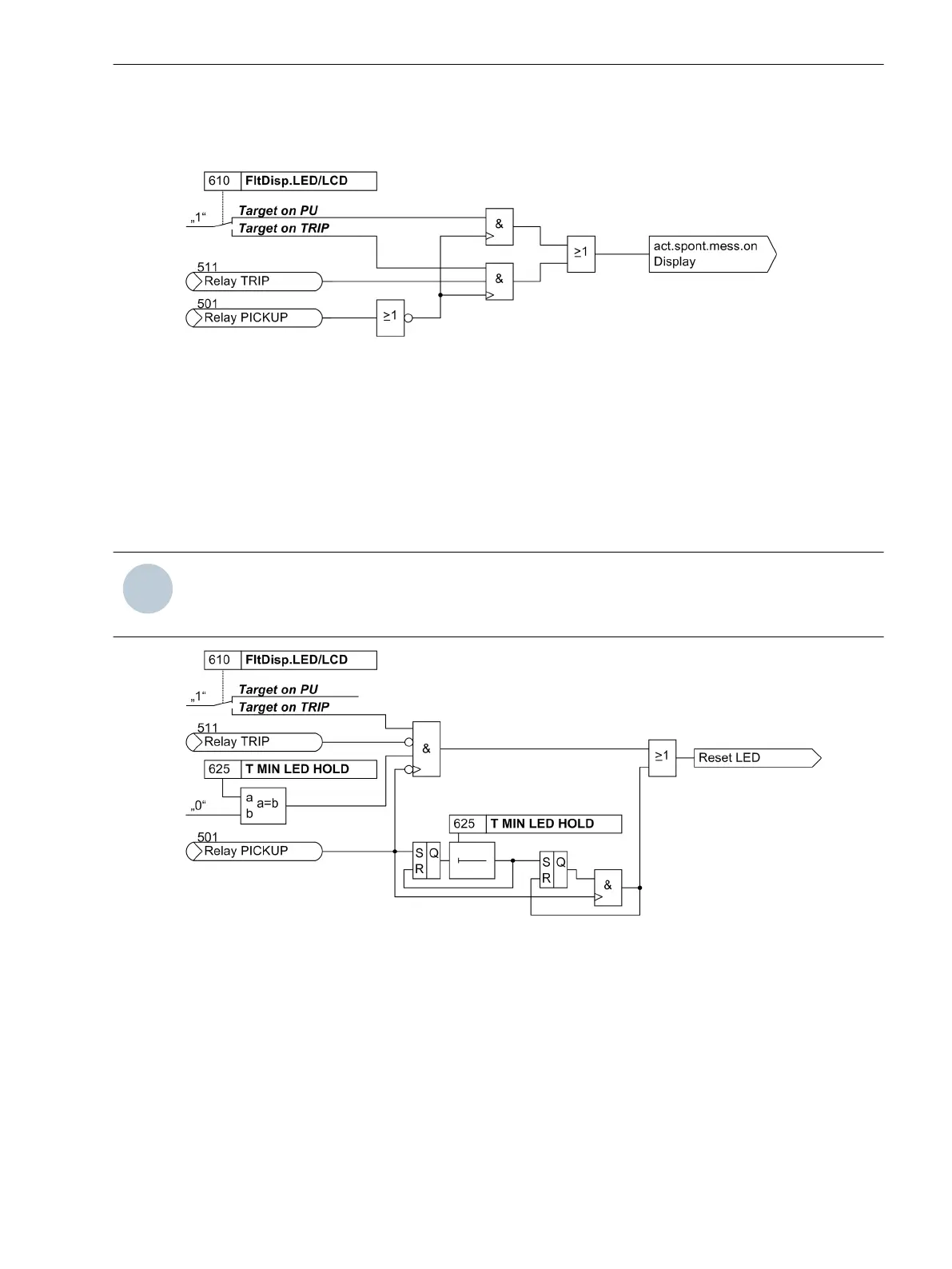
cations will appear anyway after a power system fault.
[logik-spondanmeld-display-081024, 1, en_GB]
Figure 2-1 Generation of spontaneous fault indications on the display
Reset of Stored LED / Relays
Pickup of a new protection function generally deletes all stored LED/relays so that only the information of the
latest fault is displayed at a time. The deletion of the stored LED and relays can be inhibited for a settable time
under address 625 T MIN LED HOLD. Any information occurring during this time are then combined with a
logical OR function.
Under address 610 FltDisp.LED/LCD also the information of the latest fault stored on LED and relays can
be deleted with the setting (Target on TRIP) unless this fault has lead to a trip command of the device.
NOTE
Setting the address 610 FltDisp.LED/LCD to (Target on TRIP) only makes sense if address 625 T
MIN LED HOLD is set to 0.
[logik-ruecksetz-gesp-led-081024, 1, en_GB]
Figure 2-2 Creation of the reset command for saved LED/relays
Setting Notes
Fault Annunciations
Pickup of a new protection function generally turns off any previously set displays, so that only the latest fault
is displayed at any one time. It can be selected whether the stored LED displays and the spontaneous indica-
tions on the display appear upon renewed pickup, or only after a renewed trip signal is issued. In order to
enter the desired type of display, select the submenu General Device Settings in the SETTINGS menu. At
address 610 FltDisp.LED/LCD the two alternatives Target on PU and Target on TRIP (“No trip - no
flag”) are offered.
2.1.2.2
Functions
2.1 General
SIPROTEC 4, 7VK61, Manual 29
C53000-G1176-C159-5, Edition 05.2018

 Loading...


