SIPROTEC
®
4Devices
4-23
7SA6 Manual
C53000-G1176-C156-2
CFC SIPROTEC
®
4 device information can be connected in a user-specified manner using
the programmable logic components of the DIGSI
®
4 CFC. For example, the user can
implement interlocking checks, create grouped messages, or derive limit value viola-
tion messages.
Information can be both a source and a destination in combined CFC editing. The spe-
cific logic’s inputs, e.g. the individual messages that are to be combined to form a
grouped message, must be marked in the Destination C column. The logic’s output,
the grouped message in this example, is derived from the Source C column.
Viewing the Config-
urationonthe
Operating Panel
The configuration can be seen on the operating panel of the SIPROTEC
®
4 device.
• In the main menu, select Settings → Masking (I/O).
.
• In the next menu, select Masking (I/O) → e.g. Binary Inputs.
.
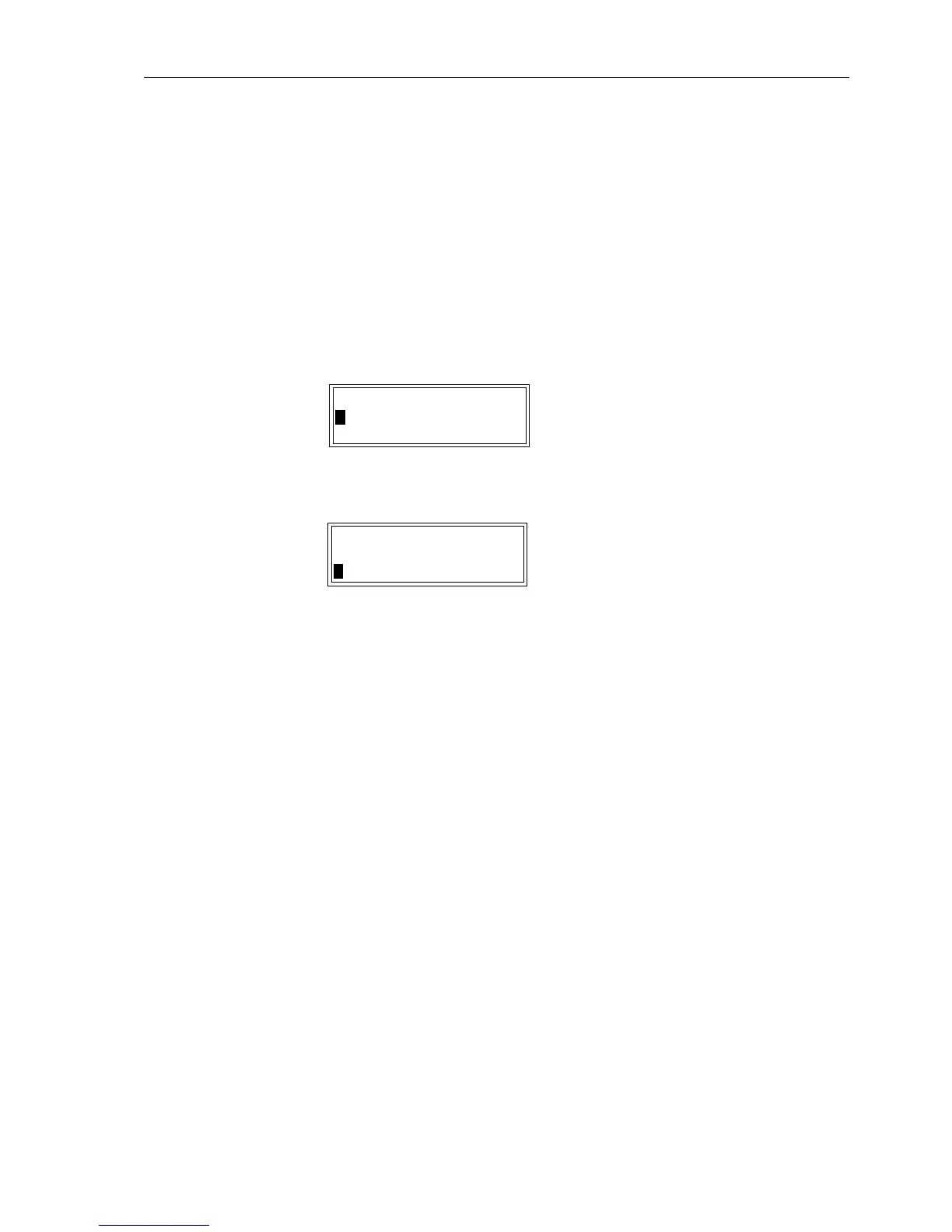
Figure 4-18 Reading the configuration using the operator control panel, example assignment
of binary input 2
MASKING (I/O) 01/03
---------------------
>Binary Inputs –> 1
>LED –> 2
BINARY INPUTS 02/20
---------------------
>Binary Input 1 –> –
>Binary Input 2 –> –

 Loading...


