Functions
6-60 7SA6 Manual
C53000-G1176-C156-2
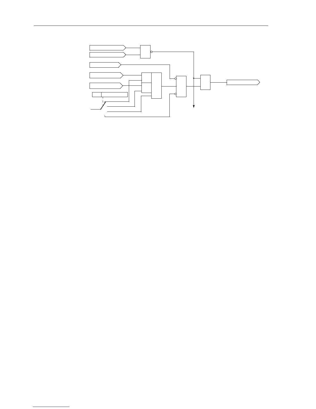
Figure 6-33 Release logic for a zone (example for Z1)
In total the following zones are available:
Independent zones:
• 1st zone (fast tripping zone) Z1 with R(Z1), X(Z1); may be delayed by T1-
1phase
and T1-multi-phase
•
2nd zone (back up zone) Z2 with R(Z2), X(Z2); may be delayed by T2-1phase
and T2-multi-phase
•
3rd zone (back up zone) Z3 with R(Z3), X(Z3);maybedelayedbyT3 DELAY
•
4th zone (back up zone) Z4 with R(Z4), X(Z4); may be delayed by T4 DELAY
•
5th zone (back up zone) Z5 with R(Z5), X(Z5)+ (forward) and X(Z5)-
(reverse); may be delayed by T5 DELAY
Dependent (controlled) zone:
• Overreaching zone Z1B with R(Z1B), X(Z1B); may be delayed by T1B-1phase
and T1B-multi-phase
6.2.4.2 Applying the Function Parameter Settings
Grading
Coordination Chart
It is recommended to initially create a grading coordination chart for the entire galvan-
ically interconnected system. This diagram should reflect the line lengths with their pri-
mary reactance X in
Ω/phase. For the reach of the distance zones, the reactances X
are the deciding quantities.
The first zone Z1 is usually set to cover 85 % of the protected line without any trip time
delay (i.e. T1 = 0.00 s). The protection clears faults in this range without additional
time delay, i.e. the tripping time is the relay basic operating time.
The tripping time of the higher zones is sequentially increased by one time grading
margin. The grading margin must take into account the circuit breaker operating time
including the spread of this time, the resetting time of the protection equipment as well
as the spread of the protection delay timers. Typical values are 0.2 s to 0.4 s. The
reachis selectedto cover up to approximately 80 % of the zone with the same set time
delay on the shortest neighbouring feeder.
Dis switched off
Dis blocked
≥1
PS blocking
reverse
forward
non-directional
inactive
Dis FD forward
Dis FD reverse
&
&
≥1
&
Op. mode Z1
„1“
&
further
zones
release of Z1
1301

 Loading...


