Hardware and Connections
2-44
7SA6 Manual
C53000-G1176-C156-2
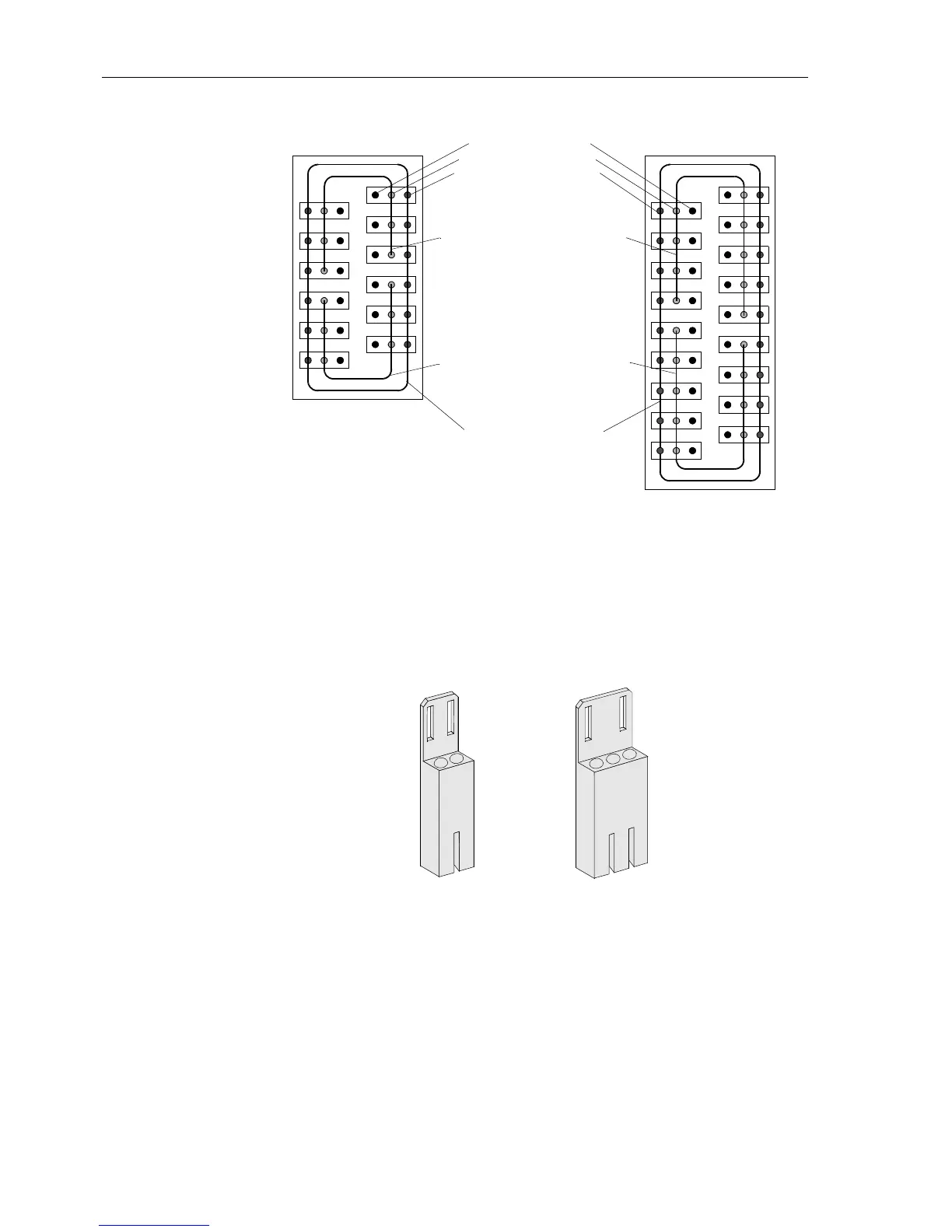
Figure 2-42 Schematic diagram of the plug-in terminal blocks
Connections to
Plug-In Terminals
Connections to plug-in terminals are made with pin connectors.
There are two versions of pin connectors:
Version 1: 2-pin connector
Version 2: 3-pin connector
Figure 2-43 2-pin connector and 3-pin connector
Ordering information for the pin connectors is provided in Section A.1 of the Appendix.
The design of the pin connectors is such that only correct connections can be made.
For example, the design of the 2-pin connector allows connection only to pins “a” and
“b”. An erroneous connection to pins “b” and “c” is excluded.
The pin connectors snap in to the plug-in terminals. The connectors can be removed
without tools.
Control wires are connected to contacts of the pin connectors. Wires with 0.5 mm
2
to
2.5 mm
2
diameter (AWG 20 to 14) can be accommodated.
Signal connection
Common connection
Shielding connection
Common connections, group 1
looped together
Common connections, group 2
looped together
Shielding connections
looped together
cba
abc
abc
abc
abc
abc
abc
cba
cba
cba
cba
cba
2
3
4
5
6
7
8
9
10
11
12
1
cba
abc
abc
abc
abc
abc
abc
cba
cba
cba
cba
cba
2
3
4
5
6
7
8
9
10
11
12
1
abc
abc
abc
cba
cba
cba
13
14
15
16
17
18
12 terminal 18 terminal
a
b
a
b
c

 Loading...


