Functions
6-497SA6 Manual
C53000-G1176-C156-2
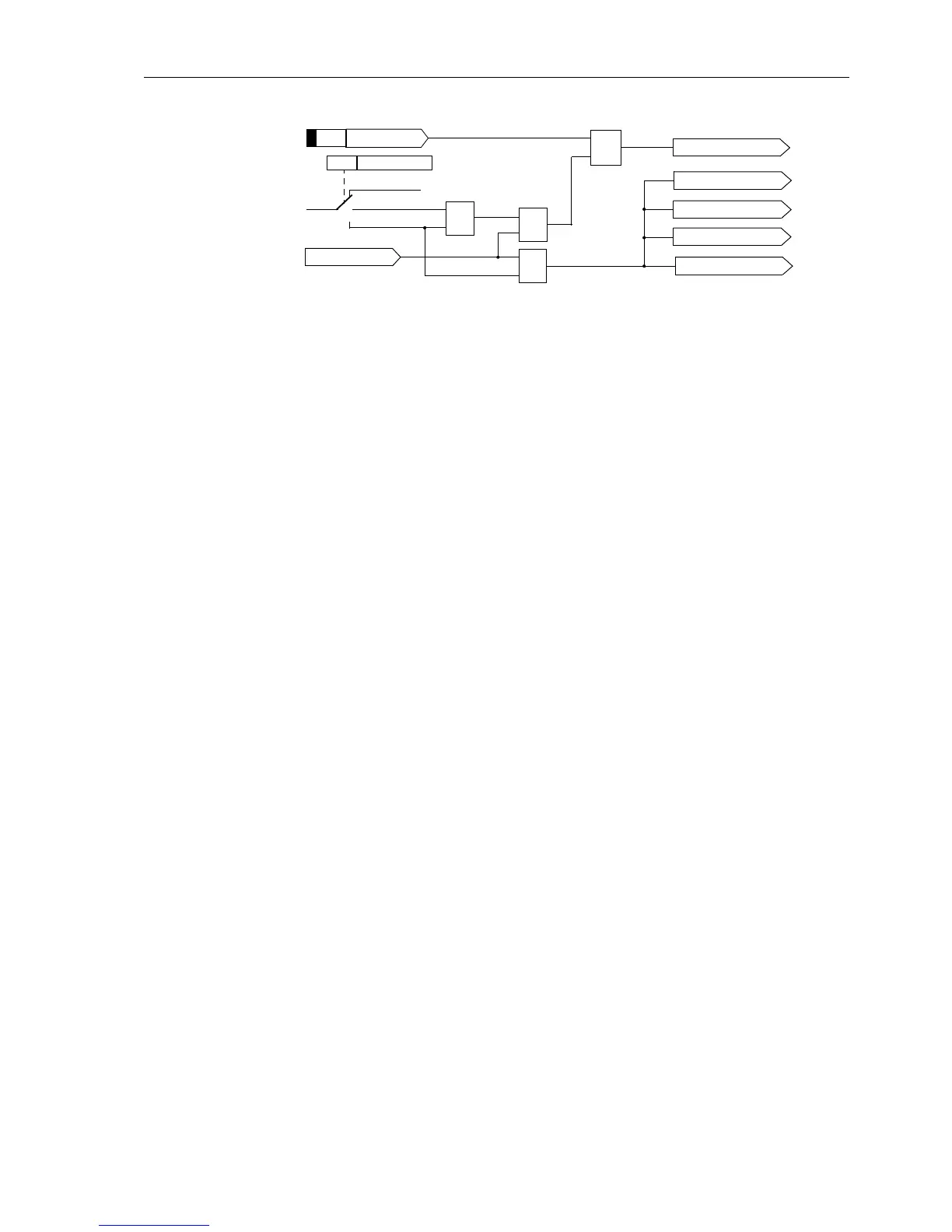
Figure 6-28 Circuit breaker closure onto a fault
6.2.3.2 Applying the Function Parameter Settings
General Function
Parameters
The distance protection can be switched on or off with the parameter in address 1201
FCT Distance ON/OFF
The minimum current for fault detection Minimum Iph> (address 1202)issetsome-
what (approx. 10 %) below the minimum short-circuit current that may occur.
The setting parameters for the treatment of earth faults
1203 3I0> Threshold and
1204 3U0> Threshold were already discussed in Sub-section 6.2.1.2.
Correction of
Measured Values
on Parallel Lines
(optional)
The mutual coupling between the two lines of a double-circuit configuration is only rel-
evant to the 7SA6 when it is applied on a double-circuit line and when it is intended to
implement parallel line compensation. A prerequisite is that the earth current of the
parallel line is connected to the I
4
measuring input of the 7SA6 and this is entered in
the configuration settings.
In this case, the setting
Paral.Line Comp = YES must be set in address 1215;oth-
erwise the presetting
NO remains.
The coupling factors were already set as part of the general protection data (Sub-sec-
tion 6.1.3), as was the reach of the parallel line compensation.
DoubleEarthFaults
in Earthed Systems
The loop selection for double earth faults is set in address 1221A 2Ph-E faults
(Phase–Phase–Earth–fault detection). This setting can only be modified with DIGSI
®
4under“Additional Settings”. In general the Block leading Ø (blocking of the
leading phase, presetting) is favourable, because the leading phase-earth loop tends
to overreach, especially in conjunction with large earth fault resistance. In certain cas-
es (fault resistance phase-phase larger than phase-earth) the setting
Block lag-
ging
Ø (blocking of the lagging phase) may be more favourable. The selection of all
affected loops with the setting
All loops allows a maximum degree of redundancy.
Alternatively,
Ø-Ø loops only may be evaluated. This ensures the most accuracy
for two phase to earth faults. Ultimately it is possible to declare the
Ø-E loops only as valid.
DoubleEarthFaults
in Non-earthed Sys-
tems
In isolated or resonant-earthed systems it must be guaranteed that the preference for
double earth faults in whole galvanically-connected systems is consistent. The double
earth fault preference is set in address
1220 PHASE PREF.2phe.
Z1B instantaneous.
SOTF zone
Zone Z1B
Inactive
PICKUP
„1“
SOTF Op. mode
≥1
&
≥1
&
Z2 instantaneous.
Z3 instantaneous.
Z4 instantaneous.
Z5 instantaneous.
ENABLE Z1B
3611
1232

 Loading...


