Functions
6-2817SA6 Manual
C53000-G1176-C156-2
6.21.1.4 Trip Circuit Supervision
TheDistanceProtection7SA6incorporatesanintegratedtripcircuitsupervisionfunc-
tion. Depending on the number of binary inputs with isolated control inputs that are still
available, a choice can be made between monitoring with one or with two binary in-
puts. If the allocation of the required binary inputs does not match the selected moni-
toring mode, a corresponding alarm is issued (“
TripC. ProgFAIL” along with the
number of the faulty monitoring circuit). If two binary inputs are used, disturbances of
the trip circuit can be detected during all switching states. With only one binary input,
faults in the circuit breaker can not be detected. If single-pole tripping is possible, a
separate trip circuit supervision can be implemented for each circuit breaker pole pro-
vided the required binary inputs are available.
Supervision Using
Two Binary Inputs
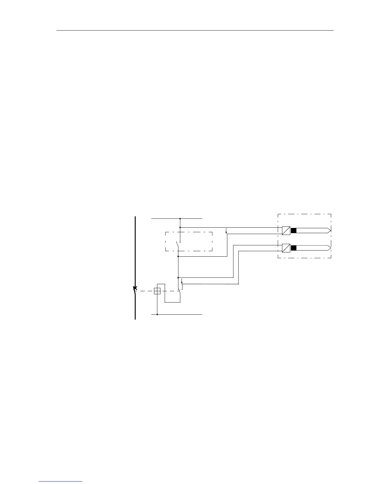
If two binary inputs are used, these are connected as shown in Figure 6-144. The one
binary input is connected in parallel to the corresponding trip relay contact of the pro-
tection while the other is connected in parallel to the circuit breaker auxiliary contacts.
A prerequisite for use of the trip circuit supervision function is that the control voltage
of the circuit breaker is greater than the sum of the minimum voltage drops across the
two binary inputs (U
C
>2·U
BImin
). As at least 19 V is necessary per binary input, the
monitoring can only be used if the trip control voltage is greater than 38 V.
Figure 6-144 Trip circuit supervision operating principle with two binary inputs
The monitoring with two binary inputs not only detects interruptions of the trip circuit
and failure of the control voltage, but also monitors the reaction of the circuit breaker
by means of the switching state of the circuit breaker auxiliary contacts.
Depending on the switching state of the trip relay and circuit breaker, the binary inputs
are initiated (logic state “H” in Table 6-12) or short circuited (logic state “L”).
The state where both binary inputs are not energized (“L”) is only present during a
short transition phase (trip relay contact is closed, but the circuit breaker has not yet
opened) if the trip circuit is healthy.
A continuous occurrence of this state is only possible during interruption or short cir-
cuit of the trip circuit as well as during failure of the battery supply voltage, or faults in
the mechanism of the circuit breaker.
L–
L+
TR
Aux2Aux1
U
BI1
U
BI2
U
C
7SA6
7SA6
TC
CB
Legend:
TR — trip relay contact
CB — circuit breaker
TC — circuit breaker trip coil
Aux1 — circuit breaker auxiliary contact
(normally open)
Aux2 — circuit breaker auxiliary contact
(normally closed)
U
C
— control voltage (tripping voltage)
U
BI1
— input voltage of the 1st binary input
U
BI2
— input voltage of the 2nd binary input
Note: The circuit breaker is shown in closed position!
>Trip C1 TripRel
>Trip C1 Bkr.Rel

 Loading...


