Functions
6-42 7SA6 Manual
C53000-G1176-C156-2
6.2.3 Calculation of the Impedances
6.2.3.1 Method of Operation
A separate measuring system is provided for each of the six possible impedance loops
L1–E, L2–E, L3–E, L1–L2, L2–L3, L3–L1. The phase-earth loops are evaluated when
an earth fault detection according to section 6.2.1 is recognized and the phase current
exceeds a settable minimum value
Minimum Iph> (address 1202). The phase-
phase loops are evaluated when the phase currents in both of the affected phases ex-
ceed the minimum value
Minimum Iph>.
A jump detector synchronizes all the calculations with the fault inception. If a further
fault occurs during the evaluation, the new measured values are immediately used for
the calculation. The fault evaluation is therefore always done with the measured val-
ues of the current fault condition.
Phase–Phase
Loops
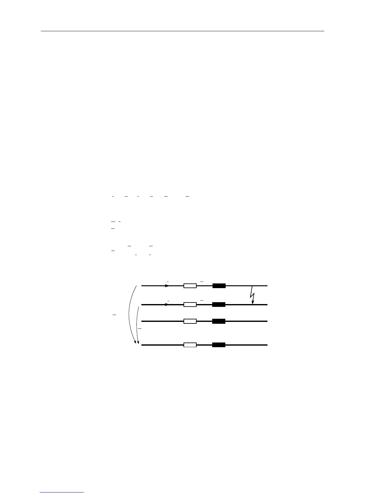
To calculate the phase-phase loop, for instance during a two-phase fault L1–L2 (Fig-
ure 6-22), the loop equation is:
where
U
, I are the (complex) measured values and
Z
= R+ jX is the (complex) line impedance.
The line impedance is computed to be
Figure 6-22 Short circuit of a phase-phase loop
The calculation of the phase-phase loop does not take place as long as one of the con-
cerned phases is switched off (during single-pole dead time), to avoid an incorrect
measurement with the undefined measured values existing during this state. A state
recognition (refer to Section 6.22) provides the corresponding block signal. A logic
block diagram of the phase-phase measuring system is shown in Figure 6-23.
I
L1
Z
L
I
L2
Z
L
U
L1–E
U
L2–E
–=⋅–⋅
Z
L
U
L1–E
U
L2–E
–
I
L1
I
L2
–
--------------------------------------=
I
L1
I
L2
Z
L
Z
L
L1
L2
L3
E
U
L2–E
U
L1–E

 Loading...


