Functions
6-282 7SA6 Manual
C53000-G1176-C156-2
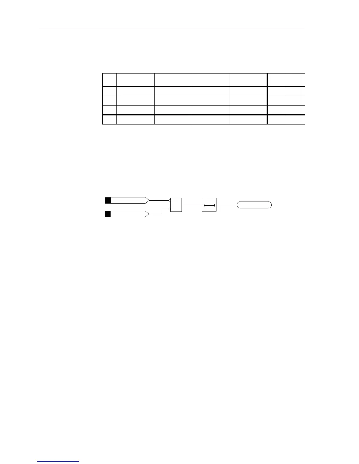
The two binary inputs are periodically interrogated to determine their state. An interro-
gation takes place every 500 ms. Only once n = 3 sequential state interrogations de-
tectafailure,willthefailurealarmbegenerated(refertoFigure6-145).Duetothis
measurement repetition the delay of the failure alarm is determined. A failure alarm
due to transient transition phases is thereby avoided. After removal of the failure in the
trip circuit, the alarm automatically resets after the same time.
Figure 6-145 Logic diagram of the trip circuit supervision with two binary inputs
Supervision Using
One Binary Input
The binary input is connected in parallel to the corresponding trip relay of the protec-
tion according to Figure 6-146. The circuit breaker auxiliary contact is bridged by
means of a high-ohmic shunt resistor R.
The control voltage of the circuit breaker should be at least twice the minimum voltage
drop across the binary input (U
C
>2·U
BImin
).Asatleast19Varerequiredforthebi-
nary input, the supervision function can be used if the trip control voltage is greater
than approximately 38 V.
An calculation example for the substitute resistance of R is shown in subsection 8.1.2,
margin “Trip Circuit Supervision”.
Table 6-12 Condition table of the binary inputs depending on the trip relay state and
CB state
No. Trip
relay
Circuit
breaker
Auxiliary
contact 1
Auxiliary
contact 2
BI 1 BI 2
1 open CLOSED closed open H L
2 open OPEN open closed H H
3 closed CLOSED closed open L L
4 closed OPEN open closed L H
&
>TripC1Tr.Rel
>TripC1Br.Rel
TT
T approx. 1 to 2 s
FAIL: Trip cir.
FNo 6855
FNo 6865
FNo 6854

 Loading...


