Configuration
5-11
7SA6 Manual
C53000-G1176-C156-2
For double commands, the first output relay is selected using DIGSI
®
4. The other out-
put relays will be automatically selected by DIGSI
®
4. In the sequence of output relays,
each TRIP command is placed before the associated CLOSE command.For
commands with feedback indications, DIGSI
®
4 reserves another line in the configu-
ration matrix for the switching device feedback indications. Here, the OPEN position
feedback is placed before the CLOSED position feedback as well.
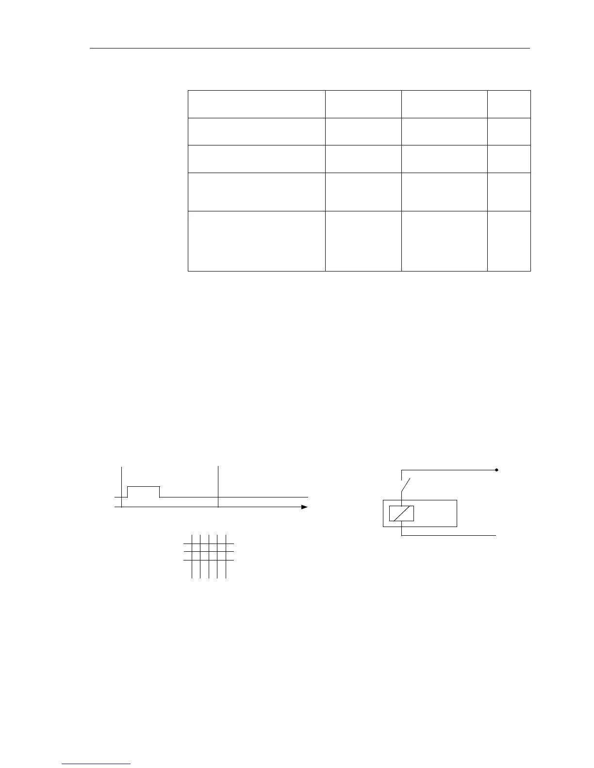
For Figures 5-4 through 5-9, the following abbreviations apply:
− C+ Relay contact for closing
− C– Relay contact for tripping
− CC Relay contact is common
− CCC Relay contact is common to a bus
− L+; L– Control voltage
Figure 5-4 Single command with single contact
Double Command with Single
Output (common to a bus)
With at least 3
relays
without feedback
with feedback
C_D2
CF_D2
Double Command with Double
Output
With 4 relays without feedback
with feedback
C_D4
CF_D4
Double Command with Double
(Close) and Single (Trip) Output
With 3 relays without feedback
with feedback
C_D12
CF_D12
Double Command Motor Control
(Anti-Clockwise Rotation /
Clockwise Rotation)
With 2 relays,
2 contacts each
without feedback
with feedback
C_D2
CF_D2
Double Command with
Single Output for
Three-Position Disconnector
Double Command with
Single Output, Negated
With 2 common
relays,
2 contacts each
for disconnector
function
(with feedback)
for earth switch
function
CF_D2
CF_D2N
Table 5-1 Most important command types
C+
X
C+
t
CLOSE
Switching
Device
C+
L+
L–
Matrix Configuration:
1
CLOSE
Command

 Loading...


