Configuration
5-14
7SA6 Manual
C53000-G1176-C156-2
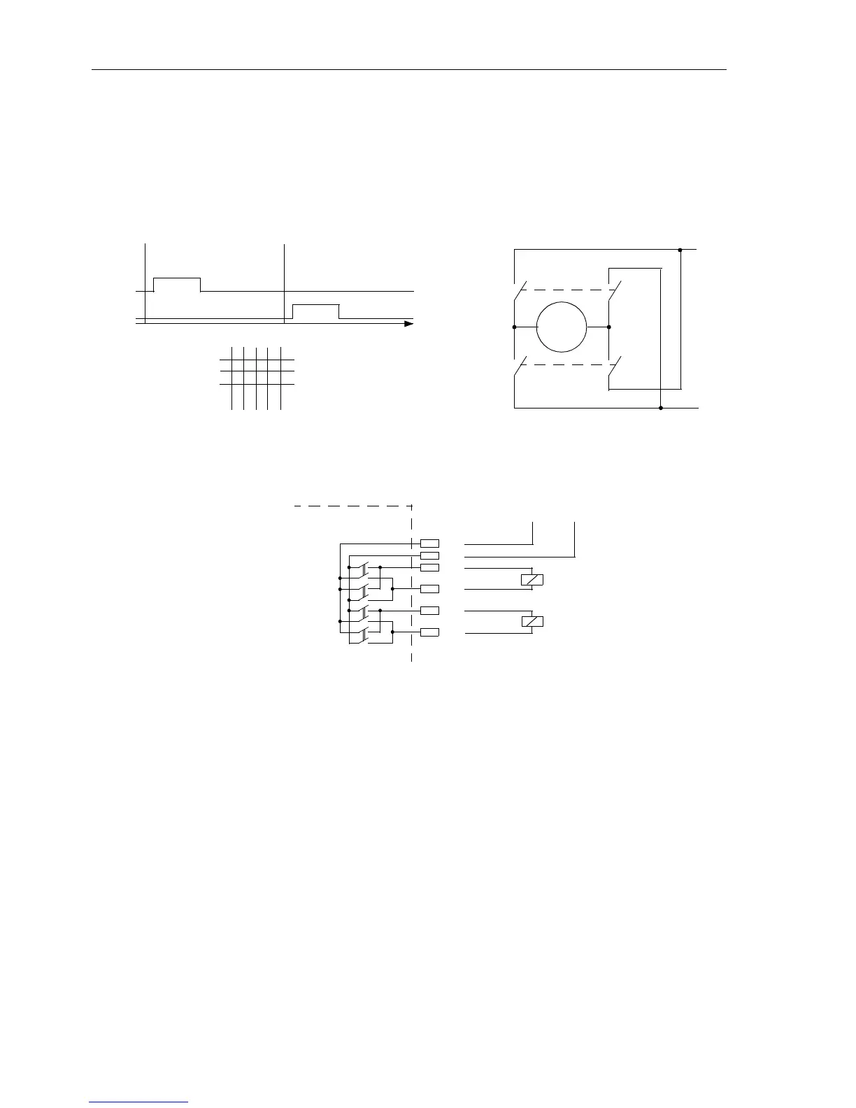
Due to the hardware platform a double command with single output via 2 relays
with one pair of contacts each can only be applied with restrictions. For this purpose
use the 2 power relays provided for motor control (only available in device versions
with power relays) (see Figure 5-11 and 5-12). Observe the internal grouping (see also
“General Diagrams” in Subsection A.2, Appendix A, Figures A-4, A-9, A-15, A-19,
A-23 and A-27).
Figure 5-10 Double command motor control (anti-clockwise rotation / clockwise rotation) via two power relays with two
contacts each
Figure 5-11 Extract of a general diagram of the variants with power relays BO 6 to BO 9 (as
an example) showing the external connections according to Figure
5-12
CLOSE
Command
C+
TRIP
Command
t
C+1
C+2
L+
L–
C–1
C–
C–2
SG
Motor
Matrix Configuration:
C+
X
6
C–
X
7
J2
(BO6)
J3
J4
K17
K18
BO7
BO8
(BO9)
J1
CLOSE
TRIP
L+L–
7SA6

 Loading...


