Configuration
5-34
7SA6 Manual
C53000-G1176-C156-2
Configuring the
System Interface as
a Destination
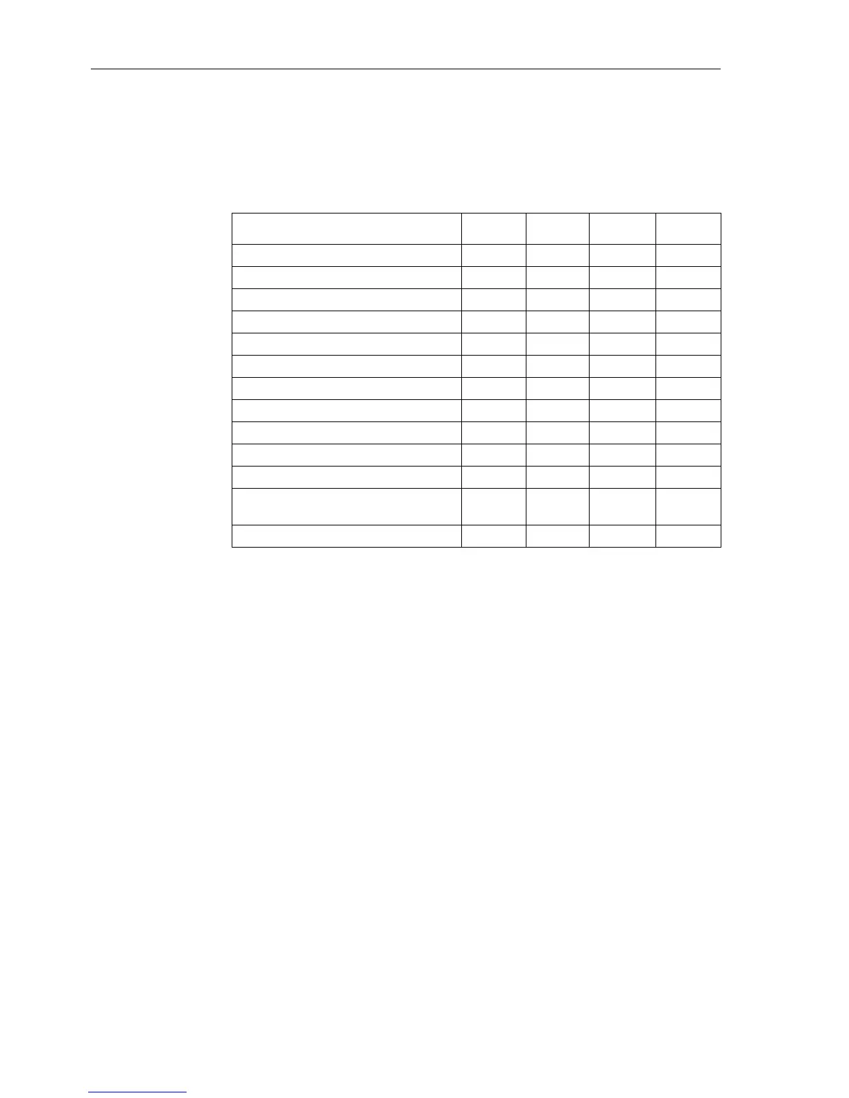
The information listed in Table 5.6 can be allocated according to the type of the system
interface. Setting an „X“ in the matrix cell the information is transferred via the system
interface to its connected components.
User-defined information (switch gears, indication, metered values etc.) can be
entered in the configuration matrix. However, it cannot be connected to a control
system via IEC 60870–5–103 and PROFIBUS FMS. For the other protocols please
use pre-defined CFC-indications (see also Table “Protocol Dependent Functions” in
the Appendix).
Configuring CFC
as a Destination
Single point, double point, and output indications, as well as limit and measured val-
ues, may be configured to CFC as the destination. This is a precondition for this infor-
mation being processed by CFC.
Configuring the
Default and Control
Display as a
Destination
Except for thresholds all informations can be allocated into both the default and the
control display. By setting an “X”inthematrixcelltheinformationcanbeusedinthe
default and control display.
Configuring the
Control as a
Destination
Single point and double point indications as well as all types of commands can be al-
located to the control as a destination. Thus they are available for the operational con-
trol in the display of the device and the DIGSI
®
4MenuControl.
Configuring the
Measured Value
Window as a
Destination
In addition to the measured values available in the relay, user defined measured and
limit values may be configured into the measured value window. These values also
become available in the device display in the corresponding measured value window
and in the DIGSI
®
4 Menu Measurement.
Tabelle 5-3 Overview of indications via the system interface
System Interface →
Information Type ↓
IEC Profibus
FMS
Profibus
DP
DNP3.0
Single Point Indications (SP) X X X X
Double Point Indications (DP) X X X X
Output Indications (OUT) X X X X
Internal Single Point Indications (IntSP) X X X X
Internal Double Point Indications (DP) X X
Transformer Tap Indication (TxTap) X
Command with/without Feedback (C_**) X X X X
Measured Value (MV) X X X
MeasuredValuewithTime(MVT) X X
Measured Value, User Defined (MVU) X
Pulse Metered Value (PMV) X X X X
Metered Value of Measured Value
(MVMV)
XXXX
Limit Value User Defined (LVU)

 Loading...


