Configuration
5-44
7SA6 Manual
C53000-G1176-C156-2
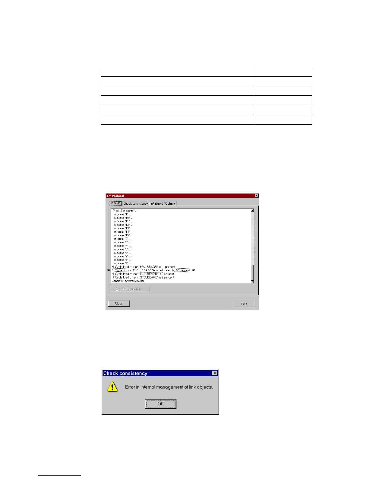
The utilized processor capacity which is available for the CFC can be checked under
Option → Reports in the register Check consistency. By scrolling, an area is
reached, where information regarding the cumulated memory consumption of the
memory reserved for CFC can be read in percent. Figure 5-40 is an example showing
an over-utilization by 56 % in the task level PLC_BEARB (marked in the Figure), while
the other task levels are within the permissible range.
Figure 5-40 Read-out of the CFC configuration degree of utilization
If the limits are exceeded during configuration of the CFC, DIGSI
®
4issuesawarning
(refer to Figure 5-41). After acknowledgement of this alarm, the system utilisation can
be viewed as described above.
Figure 5-41 Warning message on reaching the limits
Table 5-6 Processing times in TICKS required by the individual elements
Individual Element Amount of TICKS
Module, basic requirement 5
each input more than 3 inputs for generic modules 1
Connection to an input 6
Connection to an output signal 7
Additional for each configuration sheet 1

 Loading...


