Configuration
5-46
7SA6 Manual
C53000-G1176-C156-2
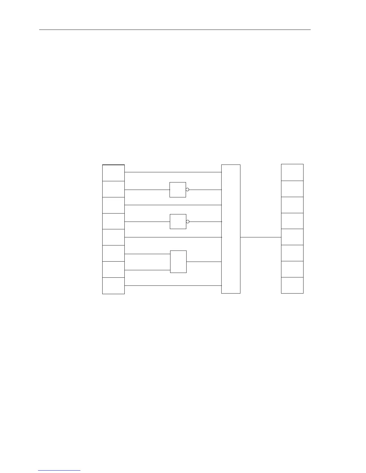
• The number of inputs of the AND gate is increased to 7.
• The CLOSE indications from the circuit breaker (CB) and from the grounding switch
(GS) are supplied to the inputs of the NOR functions.
• The OPEN indications from the circuit breaker (CB) and from the grounding switch
(GS) are supplied to the inputs of the AND function.
• The switch position indications from the disconnect switch (IS) are linked to the in-
puts of the XOR function.
• The outputs of the NOR and XOR gates are connected to the inputs of the AND
function.
• Function key 4 is linked with an input of the AND function.
• The output of the AND gate is linked to the right border column at the switching com-
mand “Disconnector Close”.
Figure 5-43 Interlocking an disconnect switch as an example of a user defined interlock pro-
tective function
Example 3 (PLC1):
Additional Logic
By using slow PLC processing, an additional, event-driven logic condition may be con-
structed which delivers indications regarding switch-gear operating status. These in-
dications may be passed externally via LEDs or relay contacts, or used as input sig-
nals for further logical links. In the example (see Figure 5-44), the output information
indication from the circuit breaker interlocking logic (CB TRIP) and a joint indication
from all protective element trip signals (Protection TRIP) are linked to a new “Circuit
Breaker Operation” message. Furthermore, the single point indication (SP) Test
Oper, which may be coupled via a binary input, is linked with an internal reusable
“Test oper.” message.
&
CB is
CB is
GS is
GS is
IS is
IS is
Door
is CLOSED
Disconnector
≥1
≥1
=1
Function
Key 4
Close
CLOSED
OPEN
CLOSED
OPEN
CLOSED
OPEN

 Loading...


