Configuration
5-59
7SA6 Manual
C53000-G1176-C156-2
To open the Time Synchronization & Format window, the user should double-
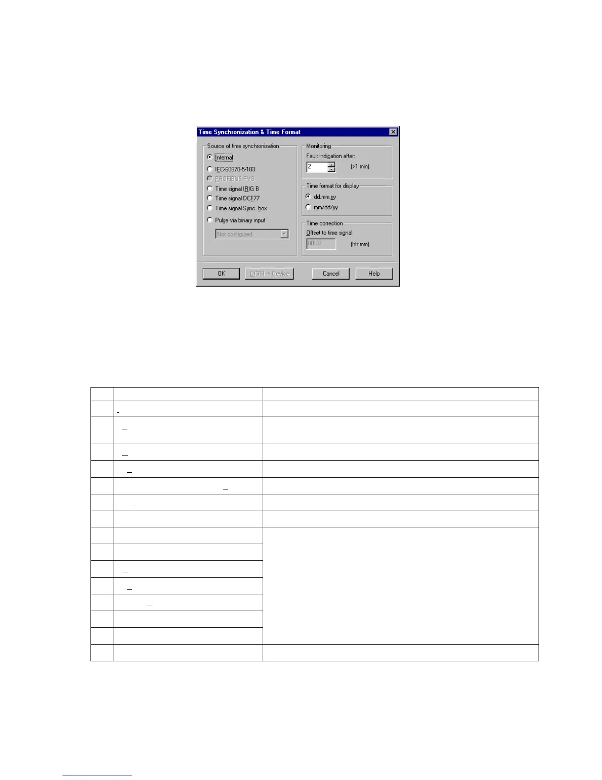
click on Time Synchronization. See Figure 5-57.
Figure 5-57 Dialogue box for time synchronization and format in DIGSI
®
4
Here you may select the time standard for internal time stamping. For the master
device you may select from the following modes:
The RTC continues running, even when the auxiliary voltage is temporary absent, by
means of an internal battery. During the device powering up, or if the auxiliary voltage
Table 5-7 Operating modes for time synchronization
Item Operating Mode Explanations
1I
nternal Clock Internal synchronization using RTC
2 IEC 60870–5–103 External synchronization using the system interface and the IEC 60870–
5–103 protocol
3 IR
IG B Time signal External synchronization using IRIG B
4 DCF77 Time signal External synchronization using DCF 77
5 SIMEAS time signal Sync. Box External synchronization using SIMEAS Sync. Box
6 Pulse via binary input External synchronization with pulse via binary input
7 Fieldbus External synchronization via fieldbus
8 Internal or Timing Master Only for devices with digital communication way:
as above No. 1 to 7; normally, however, the time is synchronized by the
absolute timing master. Only when the protection data communication
with the absolute time master fails, is the synchronization accomplished
via the indicated source.
9 IEC 60870 or Timing Master
10 IR
IG B or Timing Master
11 DCF77 or Timing Master
12 Sync. Box or Timing Master
13 Binary input or Timing Master
14 Fieldbus or Timing Master

 Loading...


