Functions
6-9
7SA6 Manual
C53000-G1176-C156-2
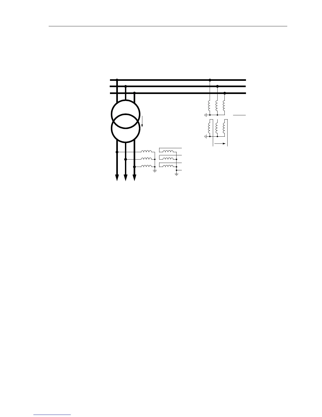
Address 215: U-line / Usync =100V/110V=0.91
Figure 6-9 Busbar voltage, measured across a power transformer
• Connection of the U
4
input to any other voltage signal U
X
, which may be processed
by the overvoltage protection function, refer to Appendix A, Figure A-46 or A-47:
Address 210 is then set: U4 transformer = Ux transformer.
It is assumed, that the Ux transformer ratio is equal to the phase voltage transform-
er ratio.
• If the U
4
input is not required, the following setting is applied:
Address 210 U4 transformer = Not connected.
Also in this case the factor Uph / Udelta (Address 211, refer to the above) is of
importance, as it is utilised for the scaling of the measurement and disturbance re-
cording signals.
Current
Transformer
Connection
The device contains four current measurement inputs, three of which are connected
to the set of current transformers. The fourth current measuring input I
4
may be utilised
in various ways:
• Connection of the I
4
input to the earth current in the starpoint of the set of current
transformers on the protected feeder (normal connection, refer to Appendix A, Fig-
ure A-31):
Address 220 is then set to: I4 transformer = In prot. line and
Address 221 to I4/Iph CT = 1.
• Connection of the I
4
input to a separate earth current transformer on the protected
feeder (e.g. a summation CT or window-type current transformer, refer to Appendix
A, e.g. Figures A-32 to A-35).
Address 220 is then set to: I4 transformer = In prot. line and
Address 221 is set to I4/Iph CT:
L1
L2
L3
U
L1
U
L2
U
L3
(any voltage)
U
E
U
sync
Feeder
Busbar
Yd5
220 kV
400 kV/220 kV
U4 transformer = Usync transf.
U-line / Usync = 0,91
Usync connect = L1–L3
ϕ Upp-Uline = 210°
220 kV/100 V
400 kV
110 V
400 kV

 Loading...


