Functions
6-21
7SA6 Manual
C53000-G1176-C156-2
K0 (> Z1) and 1123 AngleI K0(> Z1) apply to the remaining zones Z1B and Z2
up to Z5 (as seen from the relay location).
Parallel Line Mutual
Impedance
(optional)
If the device is applied to a double circuit line (parallel lines) and parallel line compen-
sation for the distance and/or fault location function is used, the mutual coupling of the
two lines must be considered. A prerequisite for this is that the earth (residual) current
of the parallel line has been connected to the measuring input I
4
of the device and that
this was configured with the power system data (Section 6.1.1) by setting the appro-
priate parameters.
The coupling factors may be determined using the following equations:
Resistance ratio: Reactance ratio:
with
R
0M
— mutual zero sequence resistance (coupling resistance) of the line
X
0M
— mutual zero sequence reactance (coupling reactance) of the line
R
1
— positive sequence resistance of the line
X
1
— positive sequence reactance of the line
These values may either apply to the entire double circuit line length or be based on
a per unit of line length, as the quotient is independent on length. Furthermore it makes
no difference if the quotients are calculated with primary or secondary values.
These setting values only apply to the protected line and are entered in the addresses
1126 RM/RL ParalLine and 1127 XM/XL ParalLine.
For earth faults on the protected feeder there is in theory no additional distance pro-
tection or fault locator measuring error when the parallel line compensation is used.
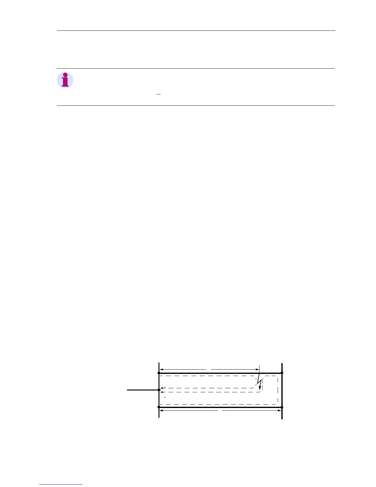
The setting in address 1128 RATIO Par. Comp is therefore only relevant for earth
faults outside the protected feeder. It provides the current ratio I
E
/I
EP
for the earth cur-
rent balance of the distance protection (in Figure 6-12 for the device at location II),
above which compensation should take place. In general, a presetting of 85% is suf-
ficient. A more sensitive (larger) setting has no advantage. Only in the case of a severe
system un-symmetry, or a very small coupling factor (X
M
/X
L
below approximately 0.4),
a smaller setting may be useful. A more detailed explanation of parallel line compen-
sation can be found in section 6.2.3.1, under distance protection.
Figure 6-12 reach with Parallel Line Compensation at II
Note:
If a combination of values is set which is not recognized by the device, it operates with
preset values K
0
=1·e
0°
. The event logs show the following information:
„DisErrorK0(>Z1)” (FNo 3655)or“Dis.ErrorK0(Z1)” (FNo 3654)
R
M
R
L
--------
1
3
---
R
0M
R
1
-----------
⋅=
X
M
X
L
--------
1
3
---
X
0M
X
1
----------
⋅=
I
E
I
EP
I
II
x
l

 Loading...


