Functions
6-44 7SA6 Manual
C53000-G1176-C156-2
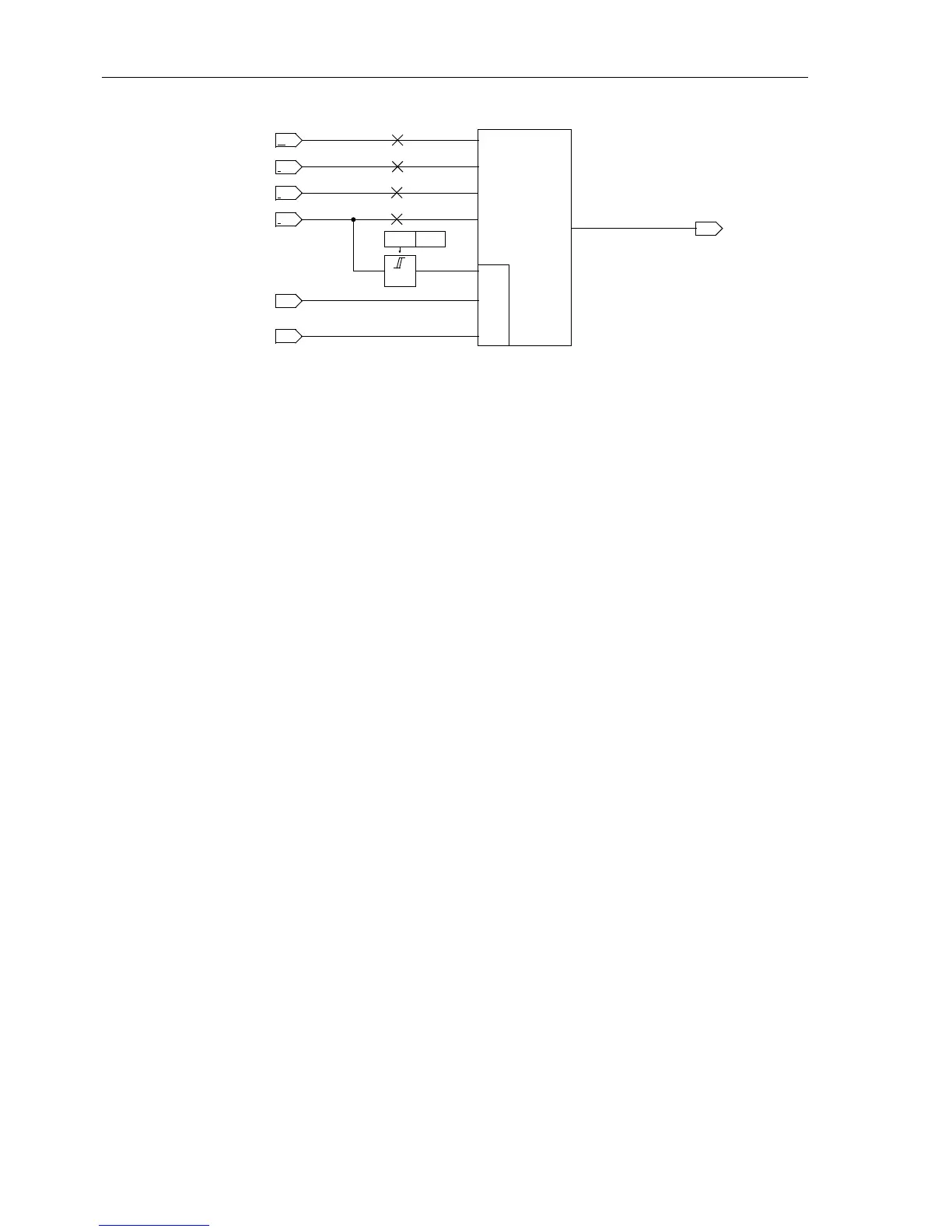
Figure 6-25 Logic of the phase-earth measuring system
Unfaulted Loops The above considerations apply to the relevant short-circuited loop. A pick-up with the
current-based fault detection modes (I, U/I, U/I/
ϕ) guarantees that only the faulty
loop(s) are released for the distance calculation. In the impedance pick-up, however,
all six loops are calculated, the impedances of the healthy loops are also influenced
by the fault currents and voltages in the short-circuited phases. During a L1–E fault for
example, the fault current in phase L1 also appears in the measuring loops L1-L2 and
L3-L1. The earth current is also measured in the loops L2–E and L3–E. Combined with
load currents which may flow, the unfaulted loops produce the so-called “apparent im-
pedances“, which have nothing to do with the actual fault distance.
These “apparent impedances” in the unfaulted loops are usually larger than the short-
circuit impedance of the faulted loop because the unfaulted loop only carries a part of
the fault current and always has a higher voltage than the faulted loop. For the selec-
tivity of the zones, the “apparent impedances” are therefore of no consequence.
Apart from the
zone selectivity,thephase selectivity is also important to achieve cor-
rect identification of the faulted phases, required to alarm the faulted phase and espe-
cially to enable single-pole automatic reclosure. Depending on the infeed conditions,
close-in short circuits may cause unfaulted loops to “see” the fault further away than
the faulted loop, but still within the tripping zone. This would cause three-pole tripping
and therefore void the possibility of single-pole automatic reclosure. As a result power
transfer via the line would be lost.
In the 7SA6 this is avoided by the implementation of a loop verification function which
operates in two steps:
Initially, the calculated loop impedances and its components (phase and/or earth) are
used to simulate a replica of the line impedance. If this simulation returns a plausible
line image, the corresponding loop pick-up is designated as a definitely valid loop.
Iftheimpedancesofmorethanonelooparenowlocatedwithintherangeofthezone,
the smallest is still declared to be a valid loop. Furthermore, all loops that have an im-
pedance which does not exceed the smallest loop impedance by more than 50 % are
declared as being valid. Loops with larger impedance are eliminated. Those loops
whichweredeclaredasbeingvalidintheinitialstage,cannotbeeliminatedbythis
stage, even if they have larger impedances.
In this manner unfaulted “apparent impedances” are eliminated on the one hand, while
on the other hand, unsymmetrical multi-phase faults and multiple short circuits are rec-
ognized correctly.
The loops that were designated as being valid are converted to phase information so
that the fault detection correctly alarms the faulted phases.
I
Lx
I
E
I
Lx
>
&
measuring
syst.
L
x
–E
from state
recognition
R
x–E
;X
x–E
U
Lx
I
EP
earth fault
recognition
1202 Iph>
(parallel line)

 Loading...


