Functions
6-82 7SA6 Manual
C53000-G1176-C156-2
number identifies the devices in the communication system since the exchange of
information between several Distance Protection systems (thus also for several
protective relay) can be executed via the same communication system.
Please make sure that the possible communications links and the existing interfaces
are in accordance with each other. If all devices are not equipped with
two protection
data interfaces, those with only
one protection data interface must be located at the
ends of the communication chain. In Figure 6-46 these are the devices with index 1
and 3. In this situation, a ring topology is possible, if all devices of a Distance
Protection system provide
two protection data interfaces.
If you work with different physical interfaces and communications links, please make
sure that every protection data interface corresponds to the projected communication
link.
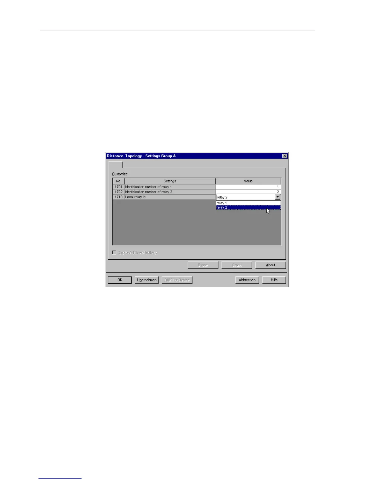
Figure 6-47 Distance Protection topology for 2 ends with 2 devices - example
For a protected object with two ends (e.g. a line) the addresses
4701 ID OF RELAY 1 and 4702 ID OF RELAY 2 are set, e.g. for device 1 the
device-ID 16 and for device 2 the device-ID 17 (Figure6-47,comparealsowithFigure
6-44 and 6-45). The indices of the devices and the device-IDs do not have to match,
as mentioned above.
For a protected object with more than two ends (and corresponding devices), further
ends are allocated to their device IDs with the parameter addresses
4703 ID OF
RELAY 3
. A maximum of 3 line ends is possible with 3 devices. Figure 6-48 gives an
example with 3 relays (compare also Figure 6-45 and 6-46) . During the configuration
of the protection functions (Section 5.1) the number of devices required for the
relevant case of application was set in address
147 NUMBER OF RELAY.DeviceIDs
can be entered for as many devices as were configured under that address after that
no further IDs are offered during configuration.

 Loading...


