Functions
6-1237SA6 Manual
C53000-G1176-C156-2
suited for a highly-sensitive earth fault detection. A fourth, definite time stage can be
implemented by setting the “inverse” stage (refer to the next paragraph) to a definite
time stage.
Inverse Time
Overcurrent
Stage 3I
0P
The logic of the inverse time stage in principle functions the same as the other stages.
This stage operates with a specially optimized digital filter that completely suppresses
all harmonic components beginning with the 2nd harmonic. Therefore it is particularly
suited for a very sensitive earth fault detection. The delay times in this case are how-
ever determined by the set characteristic (Parameter
IEC Curve), the magnitude of
the earth current and the time multiplier
3I0p Time Dial (Figure 6-70). A pre-se-
lection of the optional characteristics was already done during the configuration of the
protection functions. Furthermore, an additional fixed delay
Add.T-DELAY may be
selected. The optional characteristics are illustrated in the technical data of Section
10.5.
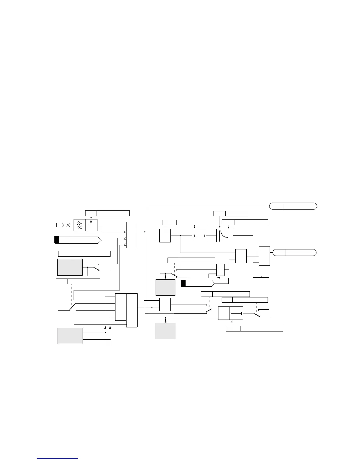
Figure 6-70showsthe logic diagram. As an example, the settingaddresses for the IEC
curves are shown in the diagram. The different setting addresses are referred to in
more detail in the setting information (Sub-section 6.7.2)
It is also possible to implement this stage as a further definite time stage. In this case
3I0p PICKUP is the pick up threshold and Add.T-DELAY the definite time delay. The
inverse time characteristic is then effectively bypassed.
Figure 6-70 Logic diagram of the 3I
0P
–stage (inverse time overcurrent protection), for example IEC curves
Inverse Time
Overcurrent Stage
with Inverse
Logarithmic
Characteristic
The inverse logarithmic characteristic differs from the other inverse characteristics
mainly by the fact that the shape of the curve can be influenced by a number of pa-
rameters. The slope
3I0p Time Dial and a time shift T I0Pmax which directly af-
fectthecurve,canbechanged.ThecurvesareillustratedinthetechnicaldateinSec-
tion 10.5, Figure 10-4.
I
E
3I
0P
3141
Yes
No
Reverse
Forward
Non-Directional
„1“
≥1
&
&
inrush
stabilization
direction
determination
forwards
reverse
&
&
Yes
No
3I0p SOTF-Trip
3148
Yes
No
3I0p Telep/BI
permissive
teleprot.
switch on
to fault
≥1
EF 3I0p TRIP
T0
3173 SOTF Time DELAY
&
&
PICKUP
PICKUP+DIRECT.
3172
&
SOTF Op. Mode
t
3I
0
3143
T0
3151
3140
1309 >EF BLOCK 3I0p
3149
1357
EF 3I0p Pickup
1369
3150
3147
≥1
>EF Inst TRIP
Add.T-DELAY
IEC Curve
3I0p PICKUP
Op. mode 3I0p
3I0p InrushBlk
3I0p Time Dial
Inactive
FNo1310

 Loading...


