Functions
6-132 7SA6 Manual
C53000-G1176-C156-2
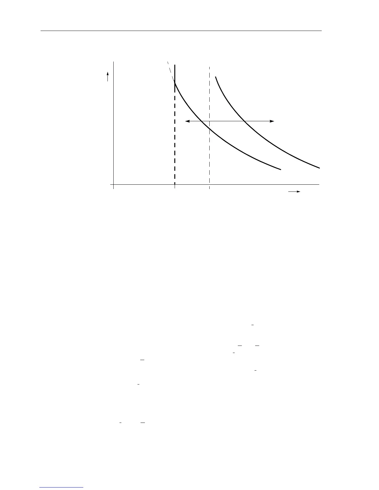
Figure 6-76 Characteristic settings of the zero sequence voltage time dependent stage —
without additional times.
Direction
Determination
The direction of each required stage was already determined when setting the differ-
ent stages.
According to the requirements of the application, the directionality of each stage is in-
dividually selected. If for instance a directional earth fault protection with a non-direc-
tional back-up stage is required, this can be implemented by setting the 3I
0
>>–stage
directional with a short or no delay time and the 3I
0
>–stagewiththesamepick-up
threshold but a longer delay time as directional back-up stage. The 3I
0
>>>–stage
could be applied as an additional high set instantaneous stage.
If a stage is to operate with teleprotection according to Section 6.8, it may operate
without delay in conjunction with a permissive scheme. In the blocking scheme, a
short delay equal to the signal transmission time, plus a small reserve margin of
approx. 20 ms is sufficient.
The direction is usually determined with the earth current
I
E
=–3I
0
as the measured
value the angle of which is compared to a polarizing quantity (Sub-section 6.7.1). The
desired polarizing signal(s) is set in
POLARIZATION (address 3160). The presetting
with Uo and IY generally also applies when only U
E
=3U
0
is used as a polarizing
signal. If there is no transformer star-point current
I
Y
connected to the device, auto-
matically only U
E
influences the direction determination.
If the direction determination must be carried out using only
I
Y
as reference signal, the
setting
with IY only is applied. This makes sense if a reliable transformer star-
point current
I
Y
is always available at the device input I
4
. The direction determination
is then not affected by disturbances in the voltage transformer secondary circuits pro-
vided that the device is equipped with a normal sensitivity current input
I
4
and the
transformer star-point current is connected to
I
4
.
If direction determination must be carried out using the negative sequence system sig-
nals 3
I
2
and 3U
2
the setting with U2 and I2 is applied. In this case, only the neg-
ative sequence system signals computed by the device are used for the direction de-
termination.
0
0 3U
0
3 × U0inv. minimal
3U0>(U0 inv)
t
a
b
c
c
a' =
3 × U0inv. minimal

 Loading...


