Functions
6-1417SA6 Manual
C53000-G1176-C156-2
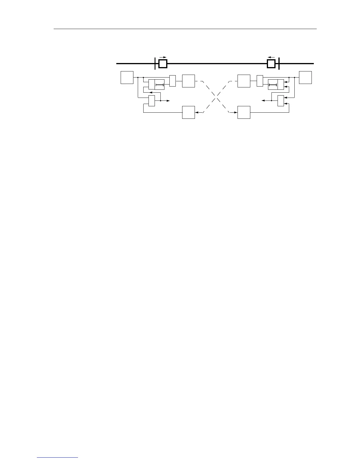
Figure 6-78 Operation scheme of the directional comparison method
Sequence Figure 6-79 shows the logic diagram of the directional comparison scheme for one line
end.
The directional comparison only functions for faults in the “forward” direction. Accord-
ingly the overcurrent stage intended for operation in the direction comparison mode
must definitely be set to
Forward (3I0... DIRECTION); refer also to Sub-section
6.7.2 under the margin heading “Teleprotection with Earth Fault Protection”.
On three terminal lines, the send signal is routed to both opposite line ends. The re-
ceive signals are then combined with a logical
AND gate,asallthreelineendsmust
transmit a send signal during an internal fault. Via the setting parameter
Line Con-
fig.
(address 3202),thedeviceisinformedastowhetherithasoneortwoopposite
line ends.
The occurrence of erroneous signals resulting from transients during clearance of ex-
ternal faults or from direction reversal resulting during the clearance of faults on par-
allel lines, is neutralized by the “Transient Blocking” (refer to Sub-section 6.8.1.4).
On feeders with only a single-sided infeed or where the system starpoint is only
earthed behind one line end, the line end without zero sequence current cannot gen-
erate a permissive signal, as fault detection does not take place there. To ensure trip-
ping by the directional comparison even in this case the device contains a special
function. This “Weak Infeed Function” (echo function) is referred to in Sub-section
6.8.1.5. It is activated when a signal is received from the opposite line end — in the
case of three terminal lines from at least one of the opposite line ends — without the
device having detected a fault.
The circuit breaker can also be tripped at the line end with no or only weak infeed. This
“Weak-Infeed Tripping” is referred to in Section 6.9.
rec.
transm.
AB
E/F.
frwd.
T
S
&
trip
rec.
&
≥1
E/F.
frwd.
T
S
&
trip
transm
&
≥1

 Loading...


