Functions
6-1817SA6 Manual
C53000-G1176-C156-2
Sensitive Earth
Fault Directional
Determination
The direction of the earth fault can be determined from the direction of the earth fault
current in relation to the displacement voltage. The only restriction is that the active or
reactive current components must be available with sufficient magnitude at the point
of measurement.
In networks with isolated starpoint, the earth fault current flows as capacitive current
from the healthy lines via the measuring point to the point of fault. This capacitive cur-
rent determines the direction.
In networks with arc suppression coils, the Petersen coil superimposes a correspond-
ing inductive current on the capacitive earth fault current when an earth fault occurs,
so that the capacitive current at the point of fault is compensated. Dependent upon the
point of measurement in the network the resultant measured current can however be
inductive or capacitive and the reactive current is therefore not suitable for the deter-
mination of direction. In this case, only the ohmic (active) residual current which re-
sults from the losses of the Petersen coil can be used for directional determination.
This earth fault ohmic current is only a few percent of the capacitive earth fault current.
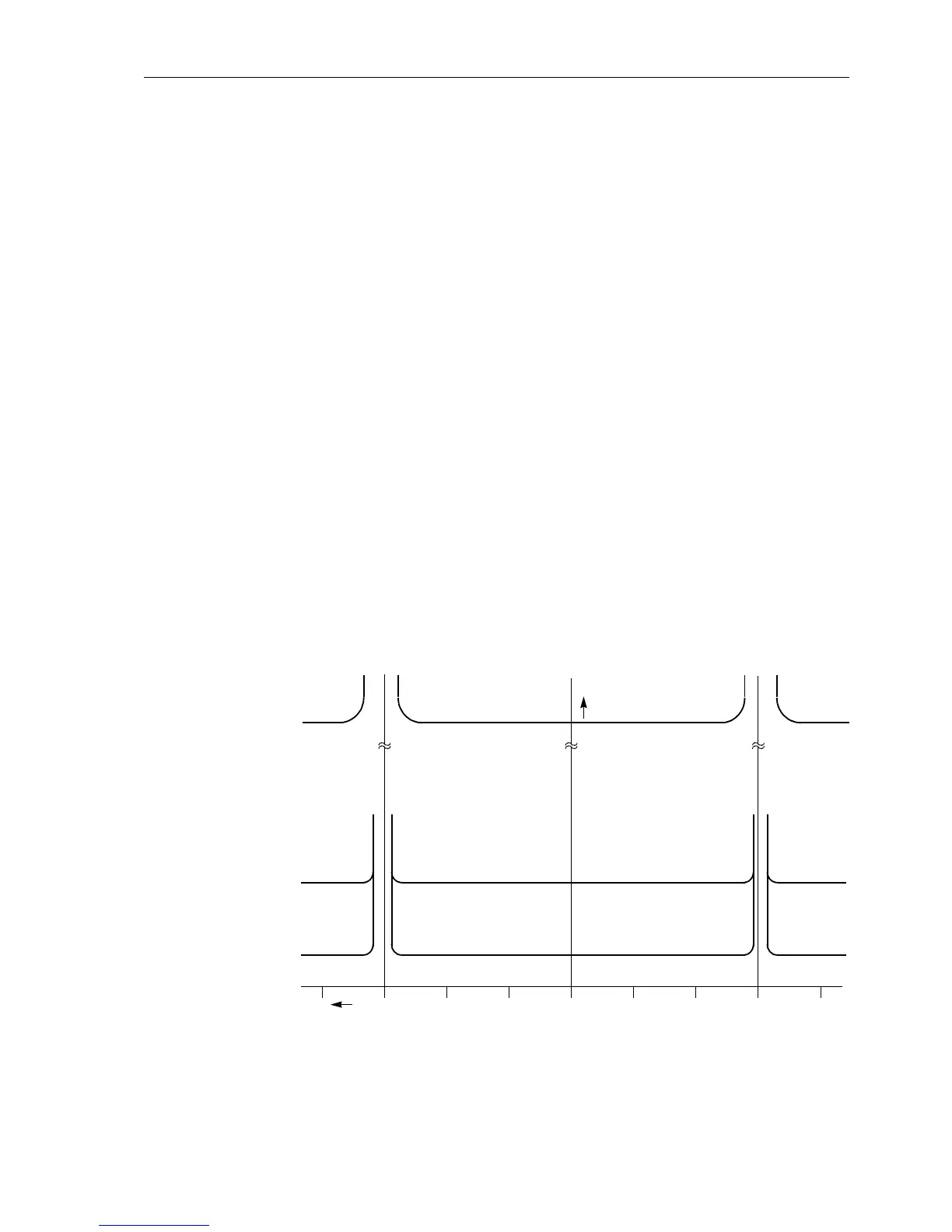
In 7SA6 the earth fault direction is determined from a highly accurate calculation of ac-
tive and reactive power using the definitions:
where T equals period of integration.
The use of an efficient calculation algorithm and simultaneous numerical filtering al-
lows the directional determination to be achieved with high accuracy and sharply de-
fined threshold limits (see Figure 6-97) and insensitivity to harmonic influences — par-
ticularly the third and fifth harmonics which are often large in earth fault currents. The
directional decision results from the signs of active and reactive power.
Figure 6-97 Directional earth fault measurement characteristic in a resonant-earthed system
Since the active and reactive component of the current – not the power – determine
the earth fault directional decision, these current components are calculated from the
P
E
1
T
---
u
E
t() i
E
t() td⋅⋅
t
tT+
ò
⋅= Q
E
1
T
---
u
E
t
π
2
---
–()i
E
t() td⋅⋅
t
tT+
ò
⋅=
and
3mA
10 mA
300 mA
0° –30° –60° –90°30°60°90°
I
Ea,
U
E
I
Er
ForwardForward ReverseReverse

 Loading...


