Functions
6-2757SA6 Manual
C53000-G1176-C156-2
Sampling
Frequency
The sampling frequency and the synchronism of the internal buffer modules is contin-
uously monitored. If deviations occur which cannot be removed by re-synchronization,
the processor system is rebooted.
Measured Value
Acquisition —
Currents
Four measuring inputs are available in the current circuits. If the three phase currents
and the earth current from the current transformer star-point or from a separate earth
current transformer on the protected circuit are connected to the device, the sum of
the four digitized currents must equal 0. Faults in the current circuits are detected if
I
F
=|I
L1
+ I
L2
+ I
L3
+k
I
· I
E
|>ΣI THRESHOLD · I
N
+ ΣI FACTOR · I
max
whereby k
I
(parameter I4/Iph CT) takes the eventual ratio difference of a separate
I
E
–current transformer into consideration (e.g. core balance CT). ΣI THRESHOLD and
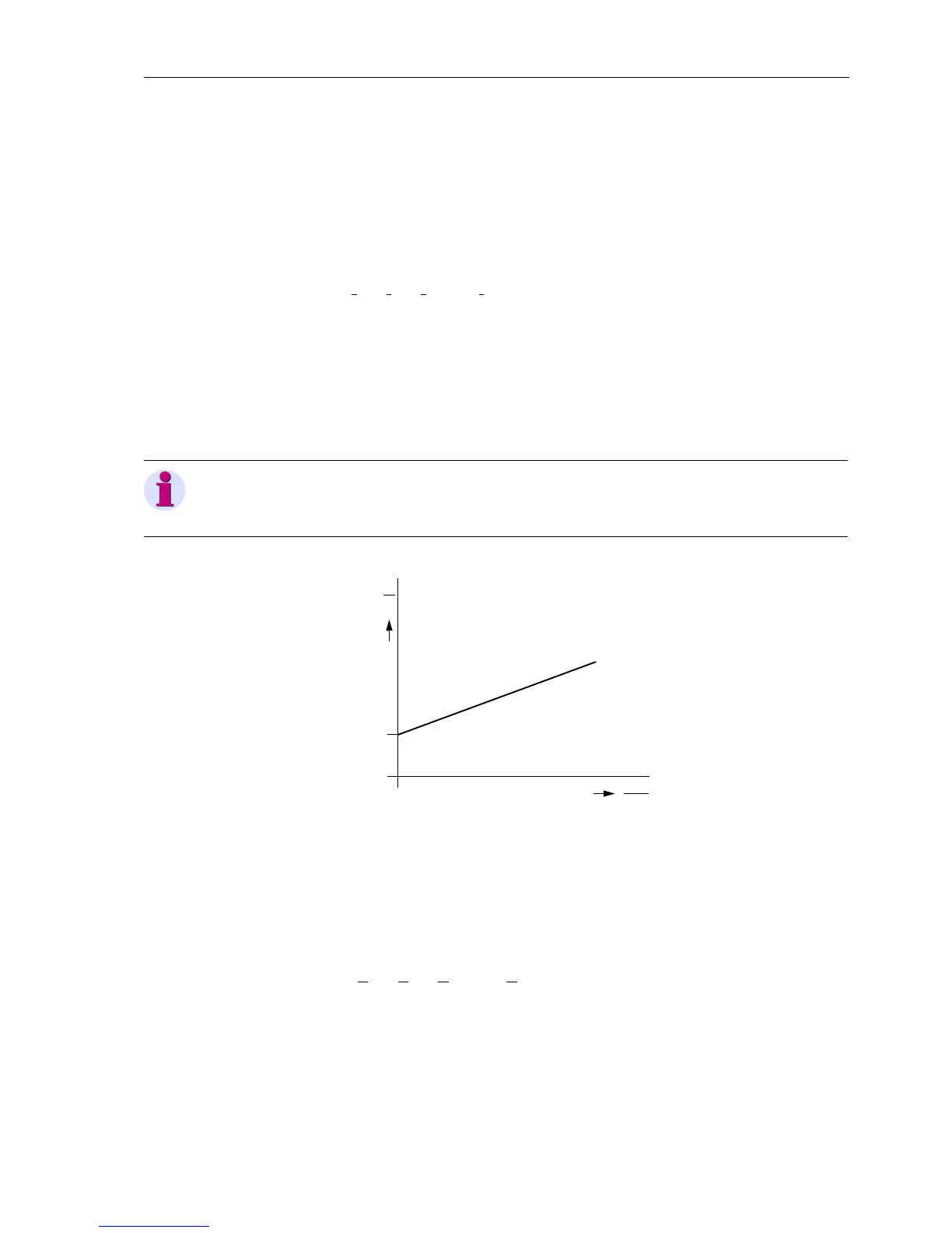
ΣI FACTOR are setting parameters. The amount ΣI FACTOR · I
max
takes the permis-
sible current proportional ratio errors of the input transducers into account which are
particularly prevalent during large fault currents (Figure 6-139). The reset ratio is ap-
prox. 97 %.
This failure is alarmed by “
Failure Σ I”.
Figure 6-139 current sum monitoring
Measured Value
Acquisition —
Voltages
Four measuring inputs are available in the voltage circuits: three for phase–earth volt-
ages as well as one input for the displacement voltage (e-n voltage of an open delta
connection) or a busbar voltage. If the displacement voltage is connected to the de-
vice, the sum of the three digitized phase voltages must equal three times the zero se-
quence voltage. Errors in the voltage transformer circuits are detected when
U
F
=|U
L1
+U
L2
+U
L3
+k
U
·U
EN
|>25V.
The factor k
U
allows for a difference of the transformation ratio between the displace-
ment voltage input and the phase voltage inputs (parameter
Uph / Udelta). The
reset ratio is approx. 97 %.
This fault is alarmed by “
Fail Σ U Ph-E”.
Note:
The current sum monitoring is only effective if the fourth current measuring input (I
4
)
is connected to measure the earth current of the protected line.
I
F
I
N
I
max
I
N
ΣI THRESHOLD
slope:
ΣI FACTOR

 Loading...


